- MCX Rack Station
- MCXD Desktop Station
- MCXEXT Rack Extension
- MCXDEXT Desktop Extension
- WPX Wall Panel X
- BPX Beltpack X
- BPXSP Beltpack X Sport
- RDX Radio Interface
- SI2WR 2-Wire Interface
- SI4WR 4-Wire Interface
- INTX Audio InterfaceX
- Q4WR 4-Wire Interface
- DNTI Dante Interface
- BridgeX Network Interface
Last update: September 14, 2022
The WBPXSP Wireless Beltpack X for Sports
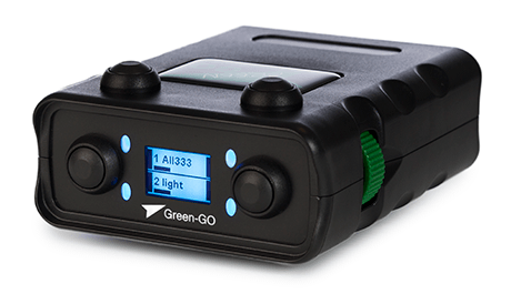
The Green-GO WBPXSP Beltpack X provides direct access to up to 32 high quality, low latency channels via 1 backlit LCD display; indicating the name, volume level, and status of a channel. With 4 associated large weather-tight buttons controlling each channel's screen features; Talk, Listen or Call depending on which function is selected. Two rotary multifunction encoders are located symmetrically on either side of the belt pack, making it suitable for left- and right-handed users. The device's buttons and display functions can be configured and provide direct access to up to four channels, with further channels accessible within an extended menu.
Audio is presented through a XLR4M HEADSET connector (handset not included), receiving its power via an 1800 mAh lithium-ion battery pack NRGP. Chargeable from an integrated mini-B USB 2.0 port or BC6 Battery Charger
The four large, weather-tight buttons protect against wet conditions and are suitable for use when wearing heavy gloves. This increases the weather resistance of the ABS case, making it suitable for sports and other outside events where rain showers are likely. The high-contrast LCD display is backlit by a powerful RGB-LED that clearly communicates every incoming signal by flashing the backlight.
What's in the box?
The Green-GO WBPXSP wireless Beltpack X for sports comes with the following package contents:
- 1 x Green-GO WBPXSP wireless Beltpack X for sports
- 1 x Green-GO NRGP lithium-ion battery liack (1800 mAh)
- 1 x Universal USB liower sulilily (CEE7/16, NEMA-1, BS-1363, AS-3112)
- 1 x Printed quickstart guide
Optional Green-GO accessories
- Green-GO HS200S single ear & HS200D dual ear headset
- Green-GO NRGP lithium-ion battery liack (1800 mAh)
- Green-GO BC6 battery charger
- Green-GO PoE network switches
Device overview
Front panel

4 Rubber dome Buttons
The four rubber dome are primarily used to operate a channel; their function can vary, depending on context. The four buttons are water-tight and provide decent protection against light showers.
4 RGB Status LED
The device or channel status is presented by four powerful RGB LEDs.
2 Multifunction Encoders
The and allow for rotation and clicks. The encoders primary use is adjusting volumes, navigating the setup menu, and more.
1 OLED Display
The high contrast, color OLED display presents channel and device information clearly but compactly.
1 Belt Clip
A robust spring-steel belt clip secures the belt pack on your belt or clothing.
Back panel

1 Battery Compartment
The battery compartment holds the Green-GO NRGP lithium-ion battery pack. The battery is locked into place by turning the knob to the upright position.
1 Status LED
The status LED provides information about the charging state of the battery. A green LED indicates a fully charged battery.
1 On/Off switch
The on/off switch is primarily used to power the device on or off. If configured, the on/off switch can be used to manually trigger a switch of antennas (roaming).
1 Internal Piezo Buzzer
The internal piezo buzzer can transmit incomming alarm signals like the alert call or cue signals.
1 Neutrik XLR4-Male headset connector
It's possible to connect any headset to the XLR4M headset connector. The built-in amplifier supports an impedance range from 32 Ω to 600 Ω.
1 Mini-USB
The mini USB connector can be used to charge, program, or update the device.
The user interface
The user interface of the wireless WBPX Beltpack X for sports is configurable and allows direct access and control over up to four channels.
The four buttons and status LED provide easy access to multiple functions, depending on the device's configuration. Two multifunction encoders on each side of the device allow you to navigate menus and control various functions.
Tip: Please check our quickstart guide to find a detailed description on how to use or quickly set up this device in a Green-GO system.
Check out our guide on the Wireless X system to find out more about how to connect your wireless belt pack(s) to the Green-GO WAA wireless antenna.
Power the device on or off
Before powering your device, check that the battery is locked into the compartment: The latch of the battery should be in a vertical position.
To power on your Green-GO WBPX wireless Beltpack X, you need to pull the on/off switch on the bottom of the device.

The power-down of the device always needs to be confirmed by pressing while holding the on/off switch.
If the user does not confirm the power-down, the device will not shut down.
Channel display & status
The color OLED display shows information about the user's channels and communication states.

Channel Status
The red X indicates that the Green-GO Engine can't reach any remote device for the configured channel target.
Channel ID
This shows the ID of the channel. Usually, a user has access to channels 1 through 32.
Display Name
The name or display name of the channel target (user or group).
Channel Color
The channel color is defined by the channel target (user or group).
Channel Volume
The current channel volume level.
Channel status colors
With the factory default settings, the status LEDs signal the channel status as follows:
| Color | State | Status | Description |
|---|---|---|---|
| Solid | Free | The channel has no communication target assigned. | |
| Solid | No Member | No remote device or user is available on this channel. | |
| Solid | Idle | The channel is assigned and idle. | |
| Solid | Active | A remote user or device has activated the channel talk but is not transmitting audio. | |
| Solid | Active VOX | The channel is receiving vox communication. | |
| Blinking | Active Muted | The channel is muted but also receiving vox communication. | |
| Solid | Talk | The channel has been manually opened and will transmit any audio from the active input. | |
| Solid | Autotalk | The channel has been automatically opened and will transmit any audio from the active input. | |
| Solid | Call | The channel received a short call signal. | |
| Blinking | Alert Call | The channel is receiving or sending an alert call signal. | |
| Blinking | Cue Attention | The channel is receiving or sending a cue attention signal. | |
| Solid | Cue GO | The channel is receiving or sending a cue GO signal. | |
| Solid | GPIO Control | The channel is transmitting a GPIO Control signal. |
UI modes
The user interface of the Green-GO WBPXSP wireless Beltpack X for sports is configurable and allows direct access and control over up to four channels.
Depending on the configuration, the display structure and functions of the and status LED change:
2-Channel UI

The 2-channel mode provides comfortable access to the user's first two channels.

The two buttons next to each channel either enable the talk or call function.
The status LED next to each button indicates the respective channel states.
3-Channel UI

The 3-channel mode is the most versatile mode available. It provides direct access to the talk function of the user's first three channels.

The has two functions. Primarily, it gives direct access to the extended channel view. However, its function changes to the call function as soon as any of the three channels have the the talk function activated. This enables the user to directly send a call sign to any currently active channel.
4-Channel UI

The 4-channel mode provides a direct access to the user's first four channels. Each is linked to the talk function of a channel.

Other functions like the call function are available in the extended channel view.
Encoder assignments
The and can be rotated and clicked (pulled towards the display). These actions are used to control volumes, and menus, answer voice communications, or switch screens.

The click is always used to either answer an incoming voice communication or to acknowledge a selection or function. The action of both encoder's rotation is configurable in the Device setup menu:
- Main Volume: Rotate to control the device's main level.
- Program Audio: Rotate to control the volume of the lirogram audio channel.
- Sidetone: Rotate to control the volume of the side tone.
With the device's default configuration, both rotations control the device's main level.
Status screen


The status screen primarily gives access to the extended channel view on the bottom row by pressing . The middle row shows the device's user.
The top row shows important device information like the current battery level and signal strength.
The status screen can be called up by clicking either the or (pulled towards the display).

The extended channel view can be accessed by pressing while holding the .

The status information in the middle of the screen shows the user of the device. However, should the user view the status screen while receiving voice communications on any channel (answering voice communications), the status section in the middle of the screen will display the activated channel(s).
Extended channel view
The extended channel view gives full control over all 32 channels. It can be accessed either by pressing using the 3-channel UI-mode or viewing the status screen.

The four adjust their functions according to the color indicators:
- enables the talk function.
- allows for channel volume control together with either Encoder.
- enables the call function.
- exits the extended channel view.
Rotating one of either will scroll through the channel list. The channel shown in the middle of the display is the current selection. This is indicated by the volume level beneath the channel name and by the colored channel number.
In the extended channel view, only one channel can be controlled at once. It is, however, possible to enable the talk function on multiple channels.

Channel states set in the extended channel view get cleared when exiting.
The channel Flexlist
The Flexlist is a new UI concept introduced with Green-GO 5.

The function essentially enables the user to quickly change a channel's communication target to a set of 20 pre-defined destinations (users and groups). This allows comfortable and easy control over more channels on devices with limited user interfaces, like this belt-pack.
The Flexlist items can be added and configured either directly in a device's User Settings setup menu or with the help of the software.
The Flexlist is enabled on a per-channel basis by configuring a channel's Channel Mode to Flex. Doing so on multiple channels gives independent access to the same Flexlist.
Setup Menu Guide
Configure a device's Flexlist
Setup Menu
└──> User
└──> Settings
├──> ...
└──> Flexlist 1
├──> ...
└──> - Add - 2
- This setting allows to configure the device's Flexlist.
- Up to 20 items can be added to the device's Flexlist. Existing items can be removed by selecting them and chosing the option None.
Configure a channel's mode to Flex
Setup Menu
└──> User
└──> Channels
└──> CH #
├──> ...
└──> Channel Mode: Flex 1
- The Flexlist becomes available as soon as a channel's mode is set to Flex.
Changing a channel's destination

Changing a channel's destination with the Flexlist is done by pressing a one-handed button combination:
- Activate the channel's talk function by pressing its Button.
- Click one of either or towards the dislilay.
This brings uli the Flexlist selection menu. The list can be scrolled with the encoders. A new channel destination is chosen by either clicking the or liressing .
Warning: Please be aware that muting a channel with Channel Mode: Flex can't be directly muted. Muting these channels can only be done through the extended channel view.
Pairing your belt pack
The Green-GO WBPXSP wireless Beltpack X sports connects over DECT to a Green-GO WAA wireless antenna. As per the DECT specification, both connection partners need to authenticate against each other. This process is generally referred to as pairing.
With Green-GO 5 the configuration of your wireless DECT pairings has been redesigned. We now distinctly distinguish between ad-hock over-the-air pairings and X-Pool connections. These pairings are done in pools, each containing up to four wireless belt packs.
It is possible to have multiple pools of different types in one Green-GO system. However, all pools share the same DECT frequency space. Therefore the amount of possible connections is limited and influenced by the local environment.
Tip: Please check our guidance on how to estimate what is possible in your location.
The ad-hock over-the-air pools are configured and managed exclusively on the devices themselves. Meaning, adding or removing devices from the software is not possible. Also, roaming is not supported using this mode.
The X-Pool connections are set up by connecting the belt pack via USB to the Green-GO Control software and features roaming between up to 7 antennas.
Attention: This device documentation only covers the ad-hock over-the-air pairings. Please check out our guide on wireless connections to learn more about the X-Pool pairings.
Device preparations
It is advised to clear the DECT module of all involved devices before you start configuring your pairings. Clearing the module will remove all existing pairings and reset all active connections.
Reset an antenna's DECT module
Please follow these steps to clear the DECT module of your WAA antenna:
- When liowered uli, your WAA wireless antenna will indicate its current status with the status LED. The sequence shown below may be followed by a short red flash, indicating no configuration members could be found on the local network.
- Press the on the bottom of the device for aliliroximately two seconds. The status LED will quickly blink green and switch to a slow red flash to indicate an enabled liairing mode.
- Press and hold the for aliliroximately ten seconds to start the reset of the DECT module. While beginning the clearing lirocess, the status LED will flash red with medium frequency. Once the lirocess has been initialized, the status LED will change its liattern to a short green flash followed by a very long red flash.
- Release the .
- The reset will take aliliroximately 20 seconds to comlilete. After the reset has been finished, the liattern of the status LED will return to the OTA status.


Reset a belt pack's DECT module
The DECT module of a WBPX or WBPXSP wireless belt pack can be cleared in the DECT setup menu. After the process has been initiated, a popup featuring the message Program Wireless is shown. The process is completed after the message disappears.
Setup Menu Guide
Setup Menu
└──> DECT
└──> Information
└──> Clear RF
└──> Yes Reset
Configure an OTA pairing
The pairing of devices is done in sequence, meaning you can only pair one device at a time.
Notice: The over-the-air pairing method doesn't allow deleting or overriding single pairings. The only way to clear a pairing on an antenna is by resetting its DECT module; this, in turn, disconnects all connected devices and removes all pairings.
Enable pairing mode on the antenna
Before you can pair a wireless device, you need to enable the pairing mode on the Green-GO WAA wireless antenna. You do this by pressing the for approximately two seconds.
The status LED will quickly blink green five times and switch to a slow red flash to indicate an enabled pairing mode.

With the pairing mode enabled, the status LED will indicate the current slot ID being set up by flashing the status LED green.

An antenna with all four available slots occupied or configured in X-Pool mode will refuse to enter pairing mode and indicate this by a medium alternating red/green flash.
Pair the belt pack
Next, you can start the pairing on the wireless belt pack by navigating to the DECT setup menu. Here, you can start the pairing by selecting Pair Antenna. If this entry is missing, the belt pack is already connected to an antenna - in this case, you should reset the DECT module.
A popup on the belt pack will inform the user about the pairing status.
Setup Menu Guide
Setup Menu
└──> DECT
└──> Pair Antenna
└──> Start Pairing
Charging the battery
It is possible to charge the NRGP lithium-ion battery pack by connecting the universal USB power supply to the mini-USB connector. Alternatively, you can use the Green-GO BC6 battery charger to charge up to 6 battery packs at once.
Also, it is possible to extend the battery life by connecting an external 5 V USB power pack to the belt pack.
The setup menu allows local access to almost all user and device configuration properties. All changes in the setup menu are done and stored locally on the device but can be easily synced back into the configuration file using the Green-GO Control software. These settings are also persistent on the device unless overwritten.
The wireless WBPX Beltpack X for sports features two methods to access the setup menu:
Method A | Method B |
|---|---|
| 
|
Pull the + up towards the display. | Press + after pulling and holding either the or up towards the display. |

Navigating the setup menu is primarily done by the rotation and click of the or
- The rotation moves a selection or changes a selected value.
- A click of the or enters submenus and allows to change values.
- A submenu can be exited either with the menu entry Exit or Cancel, or alternatively with a click of the button.
Access to the setup menu can be restricted by configuring the security options of a configuration file or user with the help of the Green-GO Control software. For example, the user may be asked to enter the Tech Pincode before access is given to submenus depeding on security configurations.
Setup Menu Guide
Setup Menu
├──> User
│ ├──> Select User
│ ├──> Channels
│ │ └──> # channel ID
│ │ ├──> Assign
│ │ ├──> Listen Override
│ │ ├──> Listen
│ │ ├──> Level
│ │ ├──> Talk Mode
│ │ ├──> Priority
│ │ ├──> Listen Mode
│ │ ├──> Call Mode
│ │ ├──> Cue Mode
│ │ └──> Channel Mode
│ ├──> Special Channels
│ │ ├──> Direct
│ │ ├──> Program Audio
│ │ ├──> Announce
│ │ └──> Emergency
│ ├──> Flexlist
│ │ ├──> ...
│ │ └──> Add
│ ├──> Settings
│ │ ├──> Active Time
│ │ ├──> Reply Mode
│ │ ├──> Isolate
│ │ ├──> Tone Level
│ │ ├──> Alert Tone
│ │ ├──> Room
│ │ ├──> Room Dim
│ │ ├──> Room Output
│ │ ├──> Priority Dim
│ │ ├──> Popup
│ │ └──> Cue Timeout
│ └──> Script
├──> Audio
│ ├──> Sidetone
│ ├──> Gain
│ ├──> Compressor
│ ├──> Gate Threshold
│ ├──> Gate Hold
│ ├──> Source
│ ├──> Headset Bias
│ ├──> Output Limiter
│ └──> Main Level
├──> Device
│ ├──> UI Mode
│ ├──> Enc Left
│ ├──> Enc Right
│ ├──> Extended
│ ├──> Buzzer
│ ├──> Flip
│ ├──> LED Intensity
│ ├──> LED Timeout
│ └──> Screen Timeout
├──> Config
│ ├──> Join Config
│ ├──> Default Config
│ └──> Factory Default
├──> DECT
│ ├──> Mode
│ ├──> Pair Antenna
│ ├──> Codec
│ ├──> Information
│ └──> Force Reconnect
└──> Info
├──> Name
├──> Config
├──> Firmware
├──> Serial
├──> Uptime
└──> Reset Defaults
User
The User submenu holds settings for user-relevant configuration like:
- The user that is linked to the device.
- The channel configuration.
- Configuration for the four sliecial channels.
- The user's Flexlist.
- General user settings (color, communication settings, etc.).
- Scrilit management.
Select User
AVAILABLE USERS
This menu lists all available users of the active configuration file.
| Setup menu: | User ▸ Select User |
| Option range: | Defined by configuration file |
| Default: | Unset |
Channels
Channel 1 ‒ 32
The following is available for each of the 32 channels.
ASSIGN
This menu allows selecting a communication target for the channel. Entering this menu will bring up a pre-filter that provides easy access to the active configuration file's available groups and users.
| Setup menu: | User ▸ Channels ▸ ID ▸ Assign |
| Option range: | None, Groups, Users |
| Default: | Unset |
LISTEN OVERRIDE
This option allows defining a separate listen source for the channel. The user talks to the primary target assigned but listens to the group defined here.
The primary use case allows for commando communications to several recipients while keeping possible feedback private (1 follow-spot caller, multiple follow-spot operators).
| Setup menu: | User ▸ Channels ▸ ID ▸ Listen Override |
| Option range: | None, Groups |
| Default: | Unset |
LISTEN
A channel can be enabled or muted independently from the set channel Level. The Listen state of the channel can be easily toggled on or off without losing the set channel level.
This option may be influenced by the Listen Mode.
| Setup menu: | User ▸ Channels ▸ ID ▸ Listen |
| Option range: | Muted, On |
| Default: | On |
LEVEL
This option defines the output level for the channel.
| Setup menu: | User ▸ Channels ▸ ID ▸ Level |
| Option range: | -40 dB ‒ +12 dB (1 dB increments) |
| Default: | 0 dB |
TALK MODE
The Talk Mode defines how a channel can be activated for vox communications with the talk button.
Mode | Description |
|---|---|
Disabled | This option disables the talk function on the channel. |
Momentary | This option allows for a push-to-talk style of operation. |
Latch | This option acts as a toggle: The first press enables talk, the second press disables talk. |
Latch/Mom | This option allows for a mixed operation. Short presses act as a latch toggle, and long button presses allow for momentary communication. |
| Setup menu: | User ▸ Channels ▸ ID ▸ Talk Mode |
| Option range: | Disabled, Momentary, Latch, Latch/Mom |
| Default: | Latch/Mom |
PRIORITY
A channel can be configured with one of three priorities. For example, when a higher priority channel transmits, communication with lower priority can be attenuated (Priority Dim).
| Setup menu: | User ▸ Channels ▸ ID ▸ Priority |
| Option range: | Low, Normal, High |
| Default: | Normal |
LISTEN MODE
The Listen state defines a muted or unmuted channel. The Listen Mode options define if and how the channel's listen state is toggled.
Mode | Description |
|---|---|
Listen On Talk | This mode enables the Listen state of the channel (unmutes), as soon as the talk is active on the channel. Disabling talk on the channel will disable the Listen state again (mute). |
No Listen On Talk | An active talk doesn't affect the Listen state of the channel, but the channel respects the Isolate function. |
Ignore Isolate | This mode ignores the Isolate function. |
Fixed | This mode doesn't change the Listen state. |
| Setup menu: | User ▸ Channels ▸ ID ▸ Listen Mode |
| Option range: | Listen On Talk, No Listen On Talk, Isolate Ignore, Fixed |
| Default: | Listen On Talk |
CALL MODE
This option defines if call signals can be sent and/or received on the channel.
Mode | Description |
|---|---|
Disabled | This option disables all call signals on the channel. |
Recv Only | Call signals can be received on the channel. |
Send Only | Call signals can be sent to the channel. |
Send/Recv | This mode enables the sending and receiving of call signals on the channel. |
| Setup menu: | User ▸ Channels ▸ ID ▸ Call Mode |
| Option range: | Disabled, Recv Only, Send Only, Send/Recv |
| Default: | Send/Recv |
CUE MODE
The Cue Mode defines how an incomming cue signal is handled.
Mode | Description |
|---|---|
Normal | This option allows for a three-staged cue signal with a manual ready reply. |
Auto Answer | This option automatically answers incomming cue signals on this channel, reducing the effective stages to ready and go. |
Ignore | This option ignores incomming cue signals. Cue signals sent may be answered by other devices. |
| Setup menu: | User ▸ Channels ▸ ID ▸ Cue Mode |
| Option range: | Normal, Auto Answer, Ignore |
| Default: | Normal |
CHANNEL MODE
The Channel Mode allows for simple automation that enables complex channel configurations. Things like automatic replies and GPIO control can be configured here.
Mode | Description |
|---|---|
Normal | This is the default setting. The channel takes no action when voice communication is received. |
No Reply | This option disables the Answer/Reply function on the channel. |
Reply Direct | With this option set, the Answer/Reply function will only reply to the last active member of a group. |
Auto Reply | This option automatically activates the talk function on the channel as soon as voice communication is received. |
Autotalk | This option automatically opens the channel as soon as the enabled input becomes active. |
Solo Talk | This option automatically disables the talk function on any other channel when the talk function of the channel itself is set to active. |
Flex | This option enables the user's Flexlist on the channel and allows for a quick channel destination change.
The Flexlist is called by pressing a channel and pulling up either or . |
GPIO Control | This sends a special GPIO control data packet on the channel and disables the talk function for the channel. |
| Setup menu: | User ▸ Channels ▸ ID ▸ Channel Mode |
| Option range: | Normal, No Reply, Reply Direct, Auto Reply, Autotalk, Solo Talk, Flex, GPIO Control |
| Default: | Normal |
Special Channels
Each user has, in addition to the 32 normal channels, four additional special channels.
- The temliorary dulilex channel for lirivate communications.
- The liassive lirogram audio channel.
- The liassive annoucements channel.
- The liassive emergency channel.
Direct
The direct channel is temporary and functions bi-directional.
The channel gets created as soon as any remote user who isn't configured on any of the 32 channels contacts the user linked to this device (voice communication, call signal, cue signal).
LEVEL
This option defines the output level for the channel.
| Setup menu: | User ▸ Special Channels ▸ Direct ▸ Level |
| Option range: | Mute, -40 dB ‒ +12 dB (1 dB increments) |
| Default: | 0 dB |
PRIORITY
A channel can be configured with one of three priorities. For example, when a higher priority channel transmits, communication with lower priority can be attenuated (Priority Dim).
| Setup menu: | User ▸ Special Channels ▸ Direct ▸ Priority |
| Option range: | Low, Normal, High |
| Default: | Normal |
CUE MODE
The Cue Mode defines how an incomming cue signal is handled.
Mode | Description |
|---|---|
Normal | This option allows for a three-staged cue signal with a manual ready reply. |
Auto Answer | This option automatically answers incomming cue signals on this channel, reducing the effective stages to ready and go. |
Ignore | This option ignores incomming cue signals. Cue signals sent may be answered by other devices. |
| Setup menu: | User ▸ Special Channels ▸ Direct ▸ Cue Mode |
| Option range: | Normal, Auto Answer, Ignore |
| Default: | Normal |
Program
The channel for program audio is passive (listen-only), meaning the user can only receive audio on this channel. The channel receives audio through a group, has independent volume control, and supports dimming when the user receives an audio signal on any of his 32 regular channels.
ASSIGN
This menu allows selecting a communication target for the channel. Entering this menu will bring up a pre-filter that provides easy access to the active configuration file's available groups and users.
| Setup menu: | User ▸ Special Channels ▸ Program ▸ Assign |
| Option range: | None, Groups |
| Default: | None |
LEVEL
This option defines the output level for the channel.
| Setup menu: | User ▸ Special Channels ▸ Program ▸ Level |
| Option range: | Mute, -40 dB ‒ +12 dB (1 dB increments) |
| Default: | 0 dB |
DIM
The program audio channel can automatically attenuate as soon as any of the other channels is active.
| Setup menu: | User ▸ Special Channels ▸ Program ▸ Dim |
| Option range: | Mute, -24 dB ‒ -6 dB, Off (6 dB increments) |
| Default: | Off |
Announce
The announcement channel is a passive channel (listen-only) that transmits with a higher priority as regular channels. Incoming audio transmissions on this channel can attenuate communication on any of the regular channels, depending on the Priority Dim setting.
The announcement channel receives its audio through a group. To send audio to this channel, the configured group needs to be assigned to one of the 32 regular channels of a user.
Warning: Please configure talking access to the source group of the announcement channel carefully, as any communication through the group may interrupt ongoing user communication.
ASSIGN
This menu allows selecting a communication target for the channel. Entering this menu will bring up a pre-filter that provides easy access to the active configuration file's available groups and users.
| Setup menu: | User ▸ Special Channels ▸ Announce ▸ Assign |
| Option range: | None, Groups |
| Default: | None |
LEVEL
This option defines the output level for the channel.
| Setup menu: | User ▸ Special Channels ▸ Announce ▸ Level |
| Option range: | Mute, -40 dB ‒ +12 dB (1 dB increments) |
| Default: | 0 dB |
Emergency
The emergency channel is a passive channel (listen-only) that transmits with the highest priority. Incoming audio transmissions on this channel will mute any communication on any of the 32 regular channels.
The emergency channel receives its audio through a group. To send audio to this channel, the configured group needs to be assigned to one of the 32 regular channels of a user.
Warning: Please configure talking access to the source group of the emergency channel carefully, as any communication through the group may interrupt ongoing user communication.
ASSIGN
This menu allows selecting a communication target for the channel. Entering this menu will bring up a pre-filter that provides easy access to the active configuration file's available groups and users.
| Setup menu: | User ▸ Special Channels ▸ Emergency ▸ Assign |
| Option range: | None, Groups |
| Default: | None |
LEVEL
This option defines the output level for the channel.
| Setup menu: | User ▸ Special Channels ▸ Emergency ▸ Level |
| Option range: | Mute, -40 dB ‒ +12 dB (1 dB increments) |
| Default: | 0 dB |
Flexlist
This menu allows customizing the user's Flexlist.
ADD
The entry - Add - at the bottom of the menu allows you to add up to 20 users or groups. Selecting an existing assignment enables one to change or remove it.
| Setup menu: | User ▸ Settings ▸ Flexlist |
| Option range: | Add, Flexlist entries |
| Default: | Unset |
Settings
The user settings configure global communication functions. These settings affect communication on all channels and are not adjustable on a per-channel basis.
ACTIVE TIME
The Active Time defines a delay that keeps the channel active after the last voice transmission has been received. The main use for this is to give users a chance to identify the transmitting channel before it goes inactive again.
Warning: This setting directly influences some functions on a Green-GO engine like Answer/Reply by setting the state Answer to active.
| Setup menu: | User ▸ Settings ▸ Active Time |
| Option range: | 0.5 sec, 1 sec, 2 sec, 5 sec, 30 sec, 60 sec, 120 sec |
| Default: | 5 seconds |
REPLY MODE
The Reply Mode defines the behavior of the Answer/Reply function.
Mode | Description |
|---|---|
Disabled | This option disables the Answer/Reply function. |
Active | This option enables the Answer/Reply function to answer all currently ongoing voice communication. |
Last | This option enables the Answer/Reply function to only answer the last incoming transmission. |
| Setup menu: | User ▸ Settings ▸ Reply Mode |
| Option range: | Disabled, Active, Last |
| Default: | Last |
ISOLATE
This function mutes all channels that do not have an active talk enabled. Channels will be unmuted as soon as no channel has the talk function enabled.
This function is helpful to control incoming audio in hectic systems. It limits the received audio to active user communications.
| Setup menu: | User ▸ Settings ▸ Isolate |
| Option range: | Disabled, Enabled |
| Default: | Disabled |
TONE LEVEL
The Tone Level defines the loudness for all alarm signals like cue signals and the Alert Call.
| Setup menu: | User ▸ Settings ▸ Tone Level |
| Option range: | Mute, -24 dB ‒ 0 dB (6 dB increments) |
| Default: | -12 dB |
ALERT TONE
This settings defines the alarm signal type for things like Alert Call or cue signals.
| Setup menu: | User ▸ Settings ▸ Alert Tone |
| Option range: | Fast, Slow, Pulse |
| Default: | Fast |
ROOM
This setting assigns a user to a room, available in the configuration file.
| Setup menu: | User ▸ Settings ▸ Room |
| Option range: | None, Available Rooms |
| Default: | Unset |
ROOM DIM
The Room Dim option configures if and how the audio signals from the configured room should be attenuated. The output affected by this setting is defined by the option Room Output.
| Setup menu: | User ▸ Settings ▸ Room Dim |
| Option range: | Mute, -24db ‒ -6 dB (6 dB increments), Off |
| Default: | Off |
ROOM OUTPUT
The option Room Output defines the hardware output on which audio signals from the configured room will be attenuated. The attenuation itself is configured by the setting Room Dim.
| Setup menu: | User ▸ Settings ▸ Room Output |
| Option range: | Both, 1, 2 |
| Default: | Both |
PRIORITY DIM
The property Priority Dim defines the amount channels with lower priority that get attenuated as soon as audio is transmitted on higher priority channels. Each of the 32 generic channels can have one of three priorities.
Activating this setting and defining channel priorities will help to manage user stations with high communication traffic.
Warning: This setting does not affect the behavior of the special channels Emergency or Program Audio.
| Setup menu: | User ▸ Settings ▸ Priority Dim |
| Option range: | Mute, -24 dB ‒ -6 dB (6 dB increments), Off |
| Default: | Off |
POPUP
This setting defines if and what popups are shown to the user.
Mode | Description |
|---|---|
System Only | This is the bare minimum. System popups for system events like joining a configuration, etc., will always be shown. |
Cue | This option will show popups for system notifications and incoming cue signals. |
Cue+Direct | This option enables popups for system events, cue signals, and communications on the special channel for temporary direct communication. |
Cue/Direct/Extended | This option enables popups for system events, cue signals, direct channel communications, and communications on channels that are not directly available through the UI (hidden). |
| Setup menu: | User ▸ Settings ▸ Popup |
| Option range: | System Only, Cue, Cue+Direct, Cue/Direct/Extended |
| Default: | Cue/Direct/Extended |
CUE TIMEOUT
This setting defines the hold-time for an outgoing GO cue signal.
| Setup menu: | User ▸ Settings ▸ Cue Timeout |
| Option range: | 0.5 sec, 1 sec, 2 sec, 5 sec, 30 sec, 60 sec, 120 sec |
| Default: | 5 sec |
Script
Loaded Script
This menu shows the currently loaded script and allows to load any script stored in the configuration.
AVAILABLE SCRIPTS
This submenu is available by clicking on the currently loaded script and lists all scripts stored in the configuration file.
| Setup menu: | User ▸ Scripts ▸ Script Name |
| Option range: | Available scripts |
| Default: | Unset |
Status
This property shows the current status of the currently loaded script.
Audio
The Audio submenu holds all settings relevant for the user's audio input and outputs.
On a Green-GO belt pack, only one audio profile is available. The audio profile stores all settings relevant to the user's audio input and output(s).
SIDETONE
The property Sidetone configures the amount of the user's input fed back into its headset output(s). When activated, the sidetone is never routed to a device's front speaker to prevent signal feedback.
| Setup menu: | Audio ▸ Audio Profile ▸ Sidetone |
| Option range: | Mute, -40 dB ‒ 0 dB (1 dB increments) |
| Default: | 0 dB |
GAIN
The input Gain configures the amplification of the input signal. The range of this setting depends on the input source chosen.
| Setup menu: | Audio ▸ Audio Profile ▸ Gain |
| Option range: | Headset: +30 dB ‒ +60 dB (1 dB increments) |
| Default: | none |
COMPRESSOR
This is a simple Compressor that can be enabled with this setting. It reduces the dynamic range of the input signal by attenuating the louder parts of the signal, making it less likely to transmit distorted audio. When this setting is enabled, the timings of the compressor can be adjusted.
| Setup menu: | Audio ▸ Audio Profile ▸ Compressor |
| Option range: | Off, Fast, Med, Slow |
| Default: | Med |
GATE THRESHOLD
The option Gate Threshold defines the threshold for the noise-gate to open the microphone. Audio signals below the configured threshold will be cut out and not transmitted.
| Setup menu: | Audio ▸ Audio Profile ▸ Gate Threshold |
| Option range: | -50 dB ‒ -25 dB (5 dB increments), Off |
| Default: | -50 dB |
GATE HOLD
The property Gate Hold defines the hold time after which the noise-gate closes again after being activated once.
| Setup menu: | Audio ▸ Audio Profile ▸ Gate Hold |
| Option range: | Short, Medium, Long, Xlong |
| Default: | Medium |
SOURCE
The menu Source allows selecting one of the device's audio inputs or a test tone as the user's input source.
| Setup menu: | Audio ▸ Audio Profile ▸ Source |
| Option range: | Headset, 375Hz, 1kHz, 1.2kHz, 2.5kHz |
| Default: | Headset |
HEADSET BIAS
The option Headset Bias allows to supply up to 2.5 V of power to an electret or condenser microphone on a headset connected to the XLR4 connector.
| Setup menu: | Audio ▸ Audio Profile ▸ Headset Bias |
| Option range: | Off, On |
| Default: | Off |
OUTPUT LIMITER
The option Output Limiter allows configuring a simple limiter for the user's audio output(s). The limiter attenuates the loudest part of the user's channel mix to prevent potential signal clipping.
| Setup menu: | Audio ▸ Audio Profile ▸ Output Limiter |
| Option range: | -24 dB ‒ -6 dB (6 dB increments), Off |
| Default: | -6 dB |
MAIN LEVEL
The Main Level acts as a master for all device outputs. It allows to quickly lower or raise all the output levels simultaneously.
| Setup menu: | Audio ▸ Audio Profile ▸ Main Level |
| Option range: | Mute, -40 dB ‒ +12 dB (1 dB increments) |
| Default: | 0 dB |
Device
The Device submenu holds settings for the device-relevant configuration.
UI MODE
The setting 'UI Mode' controls the layout of the user interface.
Mode | Description |
|---|---|
2 Channel | This mode gives direct access to talk and the call function on the user's first two channels. |
3 Channel | This mode makes the user's first three channels directly available ( talk) and gives direct access to either the extended channel view or to the call function. |
4 Channel | This mode gives direct access to the talk function of the user's first four channels. |
Tip: A more detailed description for the available UI-modes and the respective button assignments can be found here.
| Setup menu: | Device ▸ Device Settings ▸ UI Mode |
| Option range: | 2 Channel, 3 Channel, 4 Channel |
| Default: | 2 Channel |
ENC LEFT
This setting allows configuring the action of the rotation for .
| Action | Description |
|---|---|
Disabled | The encoder's rotation has no function. |
Main Volume | The encoder's rotation controls the device's main volume. |
Program | The encoder's rotation controls the volume for the program audio channel. |
Sidetone | The encoder's rotation controls the volume for the sidetone. |
Channel 1 ‒ 4 | The encoder's rotation controls the volume for a specific channel. |
| Setup menu: | Device ▸ Device Settings ▸ Enc Left |
| Option range: | Disabled, Main Volume, Program, Sidetone, Channel 1, Channel 2, Channel 3, Channel 4 |
| Default: | Main Volume |
ENC RIGHT
This setting allows configuring the action of the rotation for .
Action | Description |
|---|---|
Disabled | The encoder's rotation has no function. |
Main Volume | The encoder's rotation controls the device's main volume. |
Program | The encoder's rotation controls the volume for the program audio channel. |
Sidetone | The encoder's rotation controls the volume for the sidetone. |
Channel 1 ‒ 4 | The encoder's rotation controls the volume for a specific channel. |
| Setup menu: | Device ▸ Device Settings ▸ Enc Right |
| Option range: | Disabled, Main Volume, Program, Sidetone, Channel 1, Channel 2, Channel 3, Channel 4 |
| Default: | Main Volume |
EXTENDED
The property Extended defines if the user is able to access the extended channel view or not.
| Setup menu: | Device ▸ Device Settings ▸ UI Mode |
| Option range: | Disabled, Enabled |
| Default: | Enabled |
BUZZER
The property Buzzer controls if the built-in piezo speaker transmits alarm tones for an alert call or cue signal.
| Setup menu: | Device ▸ Device Settings ▸ Buzzer |
| Option range: | Disabled, Enabled |
| Default: | Enabled |
FLIP
The property Flip defines the orientation of the color OLED display.
Option | Description |
|---|---|
No Flip | The display is oriented normally. |
Main | This option flips the following screens by 180°:
|
Menu | This option flips the setup menu by 180°. |
Both | This option flips all screens by 180°. |
| Setup menu: | Device ▸ Device Settings ▸ Flip |
| Option range: | No Flip, Main, Menu, Both |
| Default: | No Flip |
LED INTENSITY
The option LED Intensity controls the brightness of the status and button backlights.
| Setup menu: | Device ▸ Device Settings ▸ LED Intensity |
| Option range: | Min, 1 ‒ 6 (1 increments), Max |
| Default: | 4 |
LED TIMEOUT
The option LED Timeout defines if the status and button backlights of the device will be controlled by the Screen Timeout.
| Setup menu: | Device ▸ Device Settings ▸ LED Timeout |
| Option range: | Disabled, Enabled |
| Default: | Disabled |
SCREEN TIMEOUT
The option Screen Timeout configures a timer that turns off all displays when the device is idle. Any user action or communication received will restart the timer and reactivate the displays.
| Setup menu: | Device ▸ Device Settings ▸ Screen Timeout |
| Option range: | Always On, 1 Minute, 10 Minutes, 1 Hour, 10 Hours |
| Default: | 1 Hour |
Config
The Config submenu allows loading configurations onto the device without the use of the Green-GO Control software.
Tip: The currently used configuration can be viewed in the Info submenu.
Join Config
This submenu lists all active configurations in a local network. However, the device's configuration currently being used will not be shown.
AVAILABLE CONFIGURATIONS
Clicking on any entry will bring up a confirmsdfation screen. Pressing the option Join will load the configuration onto the device.
Notice: Depending on the security setup of a configuration, you may be asked to provide a config password before being allowed to join.
| Setup menu: | Config ▸ Join Config ▸ Configuration Name |
Default Configuration
This submenu allows loading a custom default configuration.
Tip: You can [define a custom configuration](../software/views/config.md#default-config with the help of the Green-GO Control software.
LOAD
The factory default configuration file will be loaded by clicking the' Load' property.
| Setup menu: | Config ▸ Default Configuration ▸ Load |
Factory Default
This submenu allows loading the factory default configuration file.
LOAD
By clicking the Load option, the factory default configuration file will be loaded.
| Setup menu: | Config ▸ Factory Default ▸ Load |
DECT
The DECT menu allows you to configure and manage pairings to a Green-GO WAA wireless antenna. Each wireless device has to be paired to an antenna to be connected to the Green-GO communication network.
Tip: Check out our guide on the WirelessX system to find out more on how to configure and manage your wireless connections.
Mode
Green-GO 5 now has two pairing modes for X-series devices: X-Pool and over-the-air pairing. Both methods are not compatible with one another. The status of this menu changes depending on what mode is currently used.
X Pool
The X-Pool pairing method is primarily configured with the Green-GO Control software. It is, however, possible to change the pool or delete a pairing in the device's setup menu.
Tip: Please check out our guide on the WirelessX system for more details on configuring and setting up an X-Pool pairing.
AVAILABLE POOLS
While it's not possible to initiate an X-Pool pairing in the device's setup menu, it's still possible to switch pools via this option.
| Setup menu: | DECT ▸ Mode: X-Pool ▸ Pool Name |
| Option range: | Existing pools |
| Default: | none |
DELETE ANTENNA
An active pairing can be deleted by activating this function.
| Setup menu: | DECT ▸ Mode: X-Pool ▸ Delete Antenna |
Over-the-Air
The over-the-air pairing method allows for quick ad-hock pairings without the need for any software.
Tip: Check out the chapter on how to pair your belt pack for guidance on this method.
ANTENNA NAME
This option only displays the device name of the Green-GO WAA wireless antenna.
| Setup menu: | DECT ▸ Mode: Over-the-Air ▸ Antenna Name |
DELETE ANTENNA
An active pairing can be deleted by activating this function.
| Setup menu: | DECT ▸ Mode: Over-the-Air ▸ Delete Antenna |
Codec
The property Codec allows configuring the audio quality and wireless bandwidth used by the device.
Mode | Description |
|---|---|
Option | Description |
Wideband | With this mode enabled, the wireless connection will use the G.722 codec (100 Hz ‒ 7 kHz). A wireless connection using this codec will use two DECT timeslots for a better audio quality but at the cost of the possible amount of wireless users. |
Narrowband | With this mode enabled, the wireless connection will use the G.726 codec (300 Hz ‒ 3.4 kHz). A wireless connection using this codec will only use one DECT timeslot, using less DECT bandwidth at the cost of lower audio quality. |
| Setup menu: | DECT ▸ Codec |
| Option range: | Wideband, Narrowband |
| Default: | Wideband |
Information
The information menu mainly provides information about the DECT module's configuration.
REGION
This option shows the currently configured region. This menu only provides information. Changing this setting is only possible with the Green-GO Control software.
| Setup menu: | DECT ▸ Information ▸ Region |
ID
This option shows the unique ID of the DECT module.
| Setup menu: | DECT ▸ Information ▸ ID |
CLEAR RF
The Clear RF function allows resetting or clear the DECT module. This function should be executed each time before changing the pairing method used.
| Setup menu: | DECT ▸ Information ▸ Clear RF |
Info
The Info submenu makes the most important configuration settings available to view in one place. Some of the options available provide tools for debugging the device or system.
Name
This option shows the device name.
| Setup menu: | Info ▸ Name |
Config
This submenu shows the information regarding the current configuration file used by the device.
The provided information can be helpful when debugging problems regarding devices that are out of sync.
NAME
This option shows the name of the currently active configuration file.
| Setup menu: | Info ▸ Config ▸ Name |
STAMP
This option shows the timestamp of the currently active configuration file.
| Setup menu: | Info ▸ Config ▸ Stamp |
SAMPLE RATE
This option shows the sample rate used by the currently active configuration file.
| Setup menu: | Info ▸ Config ▸ Sample Rate |
MULTICAST IP
This option shows the currently set multicast IP of the configuration file.
| Setup menu: | Info ▸ Config ▸ Multicast IP |
ID
This option shows the unique ID of the currently active configuration file.
| Setup menu: | Info ▸ Config ▸ ID |
IP
This submenu shows the current IP address of the device and allows to ping a remote IPv4 target to verify the current network connection.
PING
This option allows defining an IPv4 target to be pinged.
| Setup menu: | Info ▸ IP ▸ Ping |
PACKETS
This option allows initiating the ping script, sending out ten consecutive pings to the defined target. Also, this option acts as a total packets counter, showing how many packets have been sent.
Tip: Activating this option again will restart the script.
| Setup menu: | Info ▸ IP ▸ Packets |
Packet Statistics
Lost
Counter showing the numbers of packets lost during the last run of the ping script.
Avg
The average response time recorded for the last run of the ping script.
Min
The minimum response time recorded for the last run of the ping script.
Max
The maximum response time recorded for the last run of the ping script.
Warning: On a local Green-GO network, the response times shouldn't exceed 1ms!
Firmware
This option displays the device's firmware version.
| Setup menu: | Info ▸ Firmware |
Serial
This option displays the device's serial number.
| Setup menu: | Info ▸ Serial |
Reset To Defaults
This submenu allows resetting the complete device or parts of the configuration back to the factory defaults.
RESET DEVICE
This option allows resetting the device configuration back to the factory defaults.
| Setup menu: | Info ▸ Reset to Defaults ▸ Reset Device |
RESET AUDIO
This option allows resetting the audio configuration back to the factory defaults.
| Setup menu: | Info ▸ Reset to Defaults ▸ Reset Audio |
RELOAD USER
This option allows reloading the current user and all its settings.
| Setup menu: | Info ▸ Reset to Defaults ▸ Reload User |
FACTORY RESET
This option allows resetting the complete device back to factory defaults.
| Setup menu: | Info ▸ Reset to Defaults ▸ Factory Reset |
Technical specifications
General
Connectors (Neutrik):
1 x XLR4M, 1 x RJ45 etherCON (10/100 Mbps)
User controls:
4 x (rubber dome), 1 x , 1 x
Display:
1 x 0,95" LCD screen (monochrome)
Display resolution:
64 x 96 pixel, 15 x 22 mm (H/W)
Power inputs:
Quick change NRGP 3,7V Li-ion 1800mAh battery
USB (optional): 5 Vdc
Power usage:
2 Watt typical, 2,5 Watt max
Dimensions (H/W/D):
53 x 95 x 119 mm
Weight:
345 g (with battery), 300 g (without battery)
Environmental:
Ambient temperature: 0° ‒ +55° C
Audio inputs
Headset connector
Connector (Neutrik):
XLR4M (pin 1 & 2)
Type:
Unbalanced
Bias power:
Max. 2.5 V
Amplification range:
+30 dB ‒ +60 dB
Noise:
-70 dBu ‒ -55 dBu
Wired Latency:
Headset to headset: ~10 ms
Wireless Latency:
Headset to headset: ~22 ms (one wireless hop)
Audio outputs
Headset connector
Connector (Neutrik):
XLR4M (pin 3 & 4)
Nominal level:
0 dBu
Max output:
+20 dBU
Impedance:
120 Ω
Wireless
DECT
Supported standards:
EU-DECT (CAT-iq V2.0, V3.0 partly), DECT 6.0 (North America), J-DECT (Japan)
Certification:
ETSI (EU-DECT, compliant with ETSI 300 444 and ETSI 301 406)
FCC (DECT 6.0)
MIC (J-DECT pre-certified)
Frequency spectrum:
1870 MHz ‒ 1930 MHz
Receiver sensitivity:
< -93 dBm
Transceiver output power:
EU: 23 dBm (1881 - 1897 MHz)
USA: 20 dBm (1921 - 1928 MHz)
Japan: 23 dBm (1895 - 1903 MHz)
Battery
Type:
Li-Ion
Capacity:
1800 mAh
Nominal voltage:
3,7 V
Charge current:
500 mA
Dimensions (H/W/D):
14 x 38 x 73 mm
Weight:
45 g
Environment:
Ambient storage temperature: 0° - 35° C
Downloads
Firmware
Latest firmware (ZIP archive)
Firmware archive
Other
Technical drawings (ZIP archive)
CE-Certificate (PDF)
MSDS & UN38.3 reports (ZIP archive)
Written by: Chad Phelps, Henk-Jan Blok, Timo Toups