- MCX Rack Station
- MCXD Desktop Station
- MCXEXT Rack Extension
- MCXDEXT Desktop Extension
- WPX Wall Panel X
- BPX Beltpack X
- BPXSP Beltpack X Sport
- RDX Radio Interface
- SI2WR 2-Wire Interface
- SI4WR 4-Wire Interface
- INTX Audio InterfaceX
- Q4WR 4-Wire Interface
- DNTI Dante Interface
- BridgeX Network Interface
Date of last update: December 17, 2021
The MCXD Desktop User Station
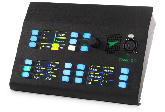
The Green-GO MCXD Desktop Station provides direct access to up to 32 high quality, low latency channels or functions over two pages of 18 fields. Controlled via 3 color TFT touchscreens indicating the name, volume level, and status of a channel or function. With 18 associated multicolor push-buttons controlling each channel's screen features; Talk, Listen, Call, or Cue depending on which function is selected. A multifunction encoder allows for easy volume adjustments and menu control.
Audio is presented through a front mounted XLR3F MIC connector (stalk microphone not included) and integrated loudspeaker or rear mounted XLR4M HEADSET connector (headset not included). The back panel includes two Ethernet LAN ports with an internal 10/100 Mbps switch and PoE power input, a 12V DC connector for an optional power supply, a set of 4-wire (1x in, 1x out) and a D-SUB 9 GPIO connection (2x in, 2x out).
The additional Green-GO MCXEXT Rack Extension or MCXDEXT Desktop Extension operates as a slave device to the MCXD. Up to 9 Green-GO Multi-Channel Rack or Desktop Extensions can be daisy-chained to one MCXD Desktop Station.
What's in the box?
The Green-GO MCXD Desktop Station comes with the following package contents:
- 1 x Green-GO MCXD desktop station
- 1 x Printed quickstart guide
Optional Green-GO accessories
- Green-GO 12V DC liower sulilily
- Green-GO GNM300 & GNM430 goose-neck microlihone
- Green-GO HS200S single ear & HS200D dual ear headset
- Green-GO lioE network switches
Device overview
Front panel

18 Multicolor Buttons
The 18 multicolor Buttons are primarily used to open a channel for voice communication or to control a function. As a secondary function, the multicolor buttons serve as a status indicator with their back-light.
3 TFT Touchscreens
Status information on channels or functions is presented to the user in a clear and compact manner on three full-color TFT touchscreens. Each display provides easy access to a bank of six freely configurable channels or functions.
1 Setup Button
The button mainly provides easy access to the setup menu.
1 Shift Button
The button accesses a second layer for channel or function operation.
1 Multifunction Encoder
The multifunction allows for rotation and clicks and is mainly used to navigate the setup menu or control specific functions like volume control.
1 Front Speaker
The MCXD desktop station comes with an internal 2-watt loudspeaker.
1 Neutrik XLR3-Female Microphone Connector
The XLR3 female microphone connector optionally supplies microphones with up to 10 V of power.
Back panel

1 12V DC Barrel Connector
The 12V DC barrel connector serves as the secondary power input and can be used with an optional power supply.
1 D-Sub 9 GPIO Connector
A GPIO D-Sub9 connector serves two in- and outputs for external control interfacing.
1 Neutrik XLR3-Female Line-Input
The balanced XLR3 male line-input connector allows injecting analog audio signals via groups into a Green-GO intercom system.
1 Neutrik XLR3-Male Line-Output
The balanced XLR3 female line-output connector allows extracting analog audio signals from a group to external receivers.
1 2-Port 10/100 Mbps Neutrik EtherCON Switch
A 2-port 10/100 Mbps network switch with Neutrik EtherCON connectors. The first network port LAN 1 accepts PoE (IEEE 802.3af) and is the primary power input for the device.
The user interface
To explain the user interface, you can divide and present it into three main areas: Channel and function control, setup and layer control, and lastly, the audio hardware consisting of the speaker and connectors for a microphone and headset.
Tip: Please check our quickstart guide to find a detailed description on how to use or quickly set up this device in a Green-GO system.
Channel and function control


The first and most prominent area comprises the three blocks consisting of six sections and six multicolor .
Each button and corresponding touchscreen section are directly linked and show channel or function information and status.
The button and related touchscreen section's function is freely configurable to accommodate every user or situational need.
Attention: Be aware that the arrangement of the displays differs from the MCX rack station. The third display is on the top right on the MCXD desktop station.
Channel status colors
With the factory default settings, the multicolor signal the channel status as follows:
| Color | State | Status | Description |
|---|---|---|---|
| Solid | Free | The channel has no communication target assigned. | |
| Solid | No Member | No remote device or user is available on this channel. | |
| Solid | Idle | The channel is assigned and idle. | |
| Solid | Active | A remote user or device has activated the channel talk but is not transmitting audio. | |
| Solid | Active VOX | The channel is receiving vox communication. | |
| Blinking | Active Muted | The channel is muted but also receiving vox communication. | |
| Solid | Talk | The channel has been manually opened and will transmit any audio from the active input. | |
| Solid | Autotalk | The channel has been automatically opened and will transmit any audio from the active input. | |
| Solid | Call | The channel received a short call signal. | |
| Blinking | Alert Call | The channel is receiving or sending an alert call signal. | |
| Blinking | Cue Attention | The channel is receiving or sending a cue attention signal. | |
| Solid | Cue GO | The channel is receiving or sending a cue GO signal. | |
| Solid | GPIO Control | The channel is transmitting a GPIO Control signal. |
Channel display
When linked to a channel, the touchscreen section displays the following information:

Channel Status
The red X indicates that the Green-GO Engine can't reach any remote device for the configured channel target.
Channel ID
This shows the ID of the channel. Usually, a user has access to channels 1 through 32.
Display Name
The name or display name of the channel target (user or group).
Channel Color
The channel color is defined by the channel target (user or group).
Channel Volume
The current channel volume level.
Setup and layer control
Next are the button, button, and multi-function . All serve in one way or another the function of configuring the device or user interface.
The button gives direct access to the setup menu. The button's main function is to switch between two operational layers of channel and function control. The multi-function allows to adjust the volumes, navigate the menus of the device, and more.

Configuring the user interface
The MCX rack and MCXD desktop station user interface is highly configurable: Any function or channel can be assigned to any and its designated section.
Button assignment

It's possible to quickly adjust the configuration of any channel or function on the user interface by using the following button combination:
- Hold down the button until it starts blinking.
- Press the desired multicolor you want to configure.
This button combination brings up the corresponding setup menu page on the third screen.
Please be aware that some functions don't have any configuration menu and therefore don't work with this button combination.
Tip: It's now possible to easily save all locally made changes into the configuration file or pre-programming the UI using the Green-GO Control software.
The channel Flexlist
The Flexlist is a new UI concept introduced with Green-GO 5.

The function essentially enables the user to quickly change a channel's communication target to a set of 20 pre-defined destinations (users and groups). This allows comfortable and easy control over more channels on devices with limited or crammed user interfaces.
The Flexlist items can be added and configured either directly in a device's User Settings setup menu or with the help of the software.
The Flexlist is enabled on a per-channel basis by configuring a channel's Channel Mode to Flex. Doing so on multiple channels gives independent access to the same Flexlist.
Setup Menu Guide
Configure a device's Flexlist
Setup Menu
└──> User
└──> Settings
├──> ...
└──> Flexlist 1
├──> ...
└──> - Add - 2
- This setting allows to configure the device's Flexlist.
- Up to 20 items can be added to the device's Flexlist. Existing items can be removed by selecting them and chosing the option None.
Configure a channel's mode to Flex
Setup Menu
└──> User
└──> Channels
└──> CH #
├──> ...
└──> Channel Mode: Flex 1
- The Flexlist becomes available as soon as a channel's mode is set to Flex.
Changing a channel's destination

Changing a channel's destination with the flex by touching the channel's section while the Screen Function is set to Listen.
This brings up the Flexlist selection menu that can be navigated by rotating the . A new channel destination is chosen by clicking the .
Warning: Please be aware that a channel with Channel Mode: Flex configured can't be muted by simply touching the section. Muting only works by clicking the while pressing the channel's Touchscreen
Functions The MCXD desktop station comes with a set of useful default functions that can be assigned to any and its section. General functions Channel 1 - 32 The channel functions enable custom arrangements of the user's channel configuration on a device. No Function
 This function can be used to completely clear a and its section to prevent accidental operation.
Screen function switches
The MCX rack and MCXD desktop station can be operated in three modes that primarily dictate a section's operation. These functions allow for switching between the three modes of operation: Listen, Call, and Cue.
Warning: The multicolor buttons normally open a channel for voice communication, regardless of the active operation mode. Toggling between modes will only affect the buttons function if the option Button Mode is set to Mode.
Listen Mode

This function switches the mode of operation to voice communication.
When active, the section of any assigned channel can be tapped to mute or unmute it. Pressing the and rotating the adjusts the channel volume.
Tip: Please be aware that this mode enables the talk function for the multicolor buttons, should the option Button Mode be set to Mode.
Call Mode

This function switches the mode of operation to call signals. When activated the section of any assigned channel can be tapped to send a call signal.
When pressed for more than 3 seconds, an Alarm Call will be sent until the touchscreen section is rereleased.
Listen / Call Mode

This function serves as a toggle to switch between the communication modes Listen and Call.
The Listen function will be prioritized when (re-)activating the function with the multicolor .
Cue Mode

This function switches the mode of operation to cue signals. When activated the section of any assigned channel can be tapped to initiate a cue signal.
The action that is performed when touching the section can be changed. Normally, an attention cue signal is sent to the selected channel. Tapping the touch screen again progresses the cue phase.
This behavior can be changed to sent direct GO cue signals by pressing the touchscreen section of the function itself. Which mode of the function is currently active is displayed in the function itself:
- Cue GO is the normal operation, described above.
- Direct GO directly sends a go signal to the selected channel. This skips the attention and ready phase.
Warning: Please be aware that outgoing cues can only be manipulated while the screen function cue mode is active. Outgoing cue signals will still be shown but can't be cleared or progressed when using other screen functions (listen or call).
Communication controls
Isolate

This function mutes all channels that do not have an active talk enabled. Channels will be unmuted as soon as no channel has the talk function enabled.
This function is helpful to control incoming audio in hectic systems. It limits the received audio to active user communications.
Warning: Please be aware that utilizing the Isolate function will cut off all channels except the channels that the user currently talks on. You will only be reachable through call or cue signals on muted channels.
Audio Profile Select

This function works as a toggle for the two device audio profiles, allowing for a quick switch.
An audio profile contains the configuration for the active input and stores the levels for the available outputs.
Tip: Using the button combination, the configuration for both audio profiles is only a click away.
Answer/Reply

This function enables the user to answer incomming voice communication. The function will always act as a momentary switch, only allowing for push-to-talk style communications.
The display will either show the linked user or the channel (s) it will reply to.
Depending on the Reply Mode setting's configuration, this function will only reply to the last opened channel or all current ongoing voice transmissions.
Warning: Be aware that this function will stay active after the last received transmission. The delay is configured with the Active Time setting.
Mic Kill

This function acts as a remote switch, disabling the talk function on all currently active users on a channel.
The Mic Kill function works with groups and users as channel targets.
Warning: Use this function with care, as it can disrupt ongoing user communication.
Cough Mute

This function allows to temporarily mute the currently active user input.
The microphone will be muted for the duration of the or press (momentary).
Channels will keep their talk enabled while the function is active.
Cue Cancel

This function allows aborting either all or selected outgoing cue signals.
The functions multicolor must be pressed together with the section of the channel to abort a selective cue signal.
The and section of the function itself must be pressed to abort all currently outgoing cue signals.
Tip: If Button Mode is configured to Mode the of a channel can be used to abort a cue signal as well.
Volume controls
These functions generally allow for volume control with the help of the .
Speaker Level

This function allows for quick adjustment of the volume of the internal speaker.
The configured volume is stored in the currently active Audio Profile.
Headset Level

This function allows for quick adjustment of the volume of a connected headset.
The configured volume is stored in the currently active Audio Profile.
Line-Output Level

This function allows for quick adjustment of the audio level for the XLR3 line output connector on the backside.
The configured volume is stored in the currently active Audio Profile.
Main Level

This function is intended to provide status information over the device's current main volume.
This function doesn't need to be used to adjust the main volume!
Direct Level

Function This function allows for quick adjustment of the volume for the special direct channel.
Program Audio Level

Function This function allows for quick adjustment of the volume for the special program audio channel.
Announcement Level

This function allows for quick adjustment of the volume for the special announcements channel.
Emergency Level

This function allows for quick adjustment of the volume for the special emergency channel.
The line in-/out engine
The MCXD desktop station comes with a secondary general purpose Green-GO Engine for the line in- and output that provides independend operation with a limited function set.
The line in- and output can be used to import external audio to a group or export a group to the line output.
Alternatively, the line in- and output can be used for the in- and output of the user's Green-GO Engine.
Warning: The XLR3 line-in and line-out ports generally work with limited functionality when compared to a standard Green-GO audio interface.
While integrations are possible with groups; extended functionality like GPIO control, cue and call signals, etc., are missing when used independently from the user.
Line Input
The line-input allows for transmitting audio through a group to other users in the system. A simple use case for the analog audio line-input on the back of the device would be external analog program audio that needs to be transmitted to multiple users in the system without the need for a dedicated audio interface.
The audio settings and destination (group) of the audio signal can be configured in the device settings.
Setup Menu Guide
Line Input
Setup Menu
└──> Device
└──> Line In/Out
└──> Line In
├──> Assign 1
├──> Gain 2
├──> Compressor 3
├──> Gate Threshold 4
└──> Gate Hold 5
- Defines the target (group) of the input.
- Defines the input gain of the signal.
- Configure a compressor on the input signal.
- Configure a noise gate on the input signal.
- Configure the gate hold timings.
Line-In as User Input
Setup Menu
└──> Audio
└──> Audio Profile 1/2
└──> ...
├──> Source: Line In 1
└──> ...
- Defines the line-in as the user input source.
Configure the line-input
Set the destination
To use the line-input to import an external audio source into the Green-GO system, we need to assign a Group that transmits the audio signal.
Setup Menu Guide
Setup Menu
└──> Device
└──> Line In/Out
└──> Line In
├──> Assign: 1
└──> ...
- Assigns a group to the line-input.
Level the input signal

Next, the input signal should be leveled to a peak value around the 0dB mark using the VU-meter on the right side of the line-in setup menu.
It is highly recommended to disable the Gate Threshold and the Compressor during this process to achieve the best results.
Setup Menu Guide
Setup Menu
└──> Device
└──> Line In/Out
└──> Line In
├──> ...
├──> Gain 1
├──> Compressor: Off 2
├──> Gate Threshold: Off 3
└──> ...
- Defines the input gain of the signal.
- Disable the compressor when leveling the input signal.
- Disable the noise gate when leveling the input signal.
Compressor and gate
The Compressor can be enabled if the dynamic input signal range is too high and the signal clips regularly.
The Gate Threshold acts as a noise-gate and can be activated to avoid transmitting background noise. Adjust this setting carefully to avoid blocking voice communication.
Setup Menu Guide
Configure the Compressor
Setup Menu
└──> Device
└──> Line In/Out
└──> Line In
├──> ...
├──> Compressor 1
└──> ...
- Configure a compressor on the input signal.
Configure the Gate
Setup Menu
└──> Device
└──> Line In/Out
└──> Line In
├──> ...
├──> Gate Threshold 1
└──> Gate Hold 2
- Configure a noise gate on the input signal.
- Configure the gate hold timings.
Configure the line-in as user input
It's possible to use the line input as user audio input. This can be useful to integrate an external microphone or audio source in the user's workflow.
To achieve this, we have to adjust the Source in one of the two available audio profiles. When configured, the input will be routed to the user's input and a potentially configured group.
Setup Menu Guide
Setup Menu
└──> Audio
└──> Profile (n)
├──> ...
├──> Source: Line In 1
└──> ...
- Configure the line input as user's input source.
Line output
The line output allows to output the communications of a group to an external receiver. A simple use case could be an announcement channel that needs to be transmitted via external speakers to a larger audience.
In addition, the line output can be used to connect a more powerful active speaker as the user's output.
Setup Menu Guide
Line Output
Setup Menu
└──> Device
└──> Line In/Out
└──> Line Out
├──> Assign 1
├──> Level 2
├──> Limiter 3
└──> Loopback 4
- Defines the source (group) for the line-output.
- Configure the signal level for the line-output.
- Configure a limiter for the output signal.
- Route the signal of the line-input to the line-output.
Line-Out as User Output
Setup Menu
└──> Audio
└──> Audio Profile n
├──> ...
├──> Line Out Level 1
└──> ...
- Routes the user's channel mix to the line output of the device.
Configure the line-output
The configuration for the line-output can be done in the Device setup menu.
Set the source
We need to Assign a group to route its communications to the line-output.
Additionally, we can route the signal of the line-input to the line-output using the Loopback setting.
Setup Menu Guide
Setup Menu
└──> Device
└──> Line In/Out
└──> Line Out
├──> Assign 1
├──> ...
└──> Loopback 2
- Defines the source (group) for the line-output.
- Route the signal of the line-input to the line-output.
Level the output signal

Next, the output signal needs to be leveled to a peak value around the 0dB mark using the VU-meter on the right side of the line-out setup menu..
It is highly recommended to disable the Limiter during this process to achieve the best results.
Setup Menu Guide
Setup Menu
└──> Device
└──> Line In/Out
└──> Line Out
├──> ...
├──> Level 1
├──> Limiter: Off 2
└──> ...
- Configure the signal level for the line-output.
- Disable the limiter while leveling the output signal.
Configure the line-out as user output
It's possible to route the user's channel mix via the line-output. This can be useful for connecting more powerful speakers or integrating the device into existing setups.
To route the user's channel mix to the line-output, we have to adjust one of the user's audio profiles. The routing can be configured by modifying the property Line Out Level.
Warning: The user's channel mix will be mixed with a potentially configured source group.
Setup Menu Guide
Setup Menu
└──> Audio
└──> Audio Profile n
├──> ...
├──> Line Out Level 1
└──> ...
- Routes the user's channel mix to the line output of the device.
The general purpose input/output
The rear panel GPIO connector enables external switches to initiate commands on the linked Green-GO Engine and also allows the device to set off external switch-controlled events using conditions such as active, talk, call, cue, etc.
The D-Sub 9 GPIO connector features two inputs and two outputs with the following pin-outs:

Each D-Sub 9 GPIO connector is directly linked to one Green-GO Engine and its associated user.

Pin 1 5 Volts of power with a maximum output current of 200mA.
Pins 6 and 7 offer common general-purpose ground.
General purpose inputs
Using the general-purpose inputs, it is possible to trigger local commands on the users Green-GO Engine. Allowing for external control over the users' channels and communication.

The inputs can be set to either Normally Open or Normally Closed. If set to Normally Open, the configured function will be executed whenever the switch is closed. If set to Normally Closed, the configured function will be executed whenever the switch is open.
The inputs actuate with contact to the ground, with a max. +5V open voltage.
Setup Menu Guide
GPIO Input
Setup Menu
└──> Device
└──> GPIO
└──> Input 1/2
├──> Function 1
├──> Channel 2
├──> Normaly 3
└──> Status 4
- Defines the function that is triggered with the GPIO input.
- Defines the target/channel for the function.
- Defines if the input is normally open or closed.
- Lists the current state of the configured input.>
Available input functions
Talk
Opens a defined channel for outgoing voice communications. This function will actuate for as long as the contacts are not in the normal state (momentary).
Call
Allows sending a call signal to a defined channel. This function will actuate for as long as the contacts are not in the normal state (momentary).
Cue Acknowledge
Allows replying to an incomming attention cue signal on any or on a defined channel with an acknowledment, setting the cue signal to ready. This function will trigger with the first pulse on the input (toggle).
Cue Abort
Allows aborting any outgoing cue signal on any or a defined channel. This function will trigger with the first pulse on the input (toggle).
Cue Attention
Allows to send an attention cue signal to a defined channel. This function will trigger with the first pulse on the input (toggle).
Cue GO
Allows to sent a direct GO cue signal to a defined channel. This function will trigger with the first pulse on the input (toggle).
Cue Clear
Allows clearing an outgoing GO cue signal on any or a defined channel. This function will trigger with the first pulse on the input (toggle).
Mic Kill
Acts as a remote switch to kill any active microphone on a defined channel (single user or all users in a group). This function will trigger with the first pulse on the input (toggle).
Warning: Configure this carefully as it will interrupt ongoing user communication.
GPIO Control
Sends a GPIO Control signal on a defined channel to trigger a remote GPIO integration.
Answer/Reply
Answers incoming communication on any or a defined channel. This function will actuate for as long as the contacts are not in the normal state (momentary).
Tip: Depending on the setting Reply Mode this function either answers the last incomming voice communication or all ongoing voice communications.
Cough Mute
Mutes the currently active user input. This function will actuate for as long as the contacts are not in the normal state (momentary).
General purpose outputs
Using the general-purpose outputs, it is possible to trigger and control external devices or relays with a set of functions and or states. Allowing to extend the control outside of the Green-GO network.

The general-purpose output is a floating optocoupler. When activated, it's capable of passing 8mA with a maximum of 50 Volts. It can be used to switch third-party logic inputs directly, a signal-led, or with some extra circuitry drive bigger loads like relays.
As with the inputs, the outputs can be set to either Normally Open or Normally Closed, controlling the configuration's idle state.
Setup Menu Guide
GPIO Output
Setup Menu
└──> Device
└──> GPIO
└──> Output
├──> Function 1
├──> Channel 2
├──> Normaly 3
└──> Test 4
- Defines the function that triggers the output.
- Defines the source/channel for the function.
- Defines if the output is normally open or closed.
- Allows testing the configuration manually.
Available output functions
Channel Active
Activates as soon as any or one defined channel has the state active but isn't yet transmitting. The output actuates for the duration of this state (momentary).
Tip: Be aware that this function is influenced by the user setting Active Time. A channel will stay active for the configured duration after no signal is received.
Channel Vox
Activates as soon as any or one defined channel of the user receives active voice communication. The output actuates for the duration of this state (momentary).
Tip: Be aware that this function is influenced by the user setting Active Time. A channel will stay
Talk Enabled
Activates as soon as any or one defined channel of the user is manually opened to transmit voice communication. The output actuates for the duration of this state (momentary).
Call
Activates as soon as any or one defined channel receives a call signal. The output actuates once as soon as the state changes (toggle).
Alert Call
Activates as soon as any or one defined channel receives an alert call signal. The output actuates once as soon as the state changes (toggle).
GPIO Control
Activates as soon as any or one defined channel receives an GPIO Control signal. The output actuates once as soon as the state changes (toggle).
Driving an LED

A signal LED can be driven directly with one GPIO output, utilizing pin 1 as a 5 Volt power supply.
A series of resistors must be added to the circuit to limit the current to a maximum of 5mA. The resistor needed depends on the LED used.
Your circuit for this application could look like the schematics to the left.
Driving a relay

A simple circuit with a transistor is needed to drive an external relay with a current higher than 5mA through a GPIO output.
The schematics to the right can be used as an example.
Warning: Please be aware that the resistor between the power supply and pin 4 or 5 is dependent on the voltage of the power supply used!
The setup menu allows local access to almost all user and device configuration properties. All changes in the setup menu are done and stored locally on the device but can be easily synced back into the configuration file using the Green-GO Control software. These settings are also persistent on the device unless overwritten.
The setup menu is accessed with the dedicated button. The multi-function is used to navigate the menu lists:
- The rotation moves a selection or changes a selected value.
- A click of the enters submenus and allows to change values.
- A submenu can be exited either with the menu entry Exit or Cancel, and alternatively with the button.
Access to the setup menu can be restricted by configuring the security options of a configuration file or user with the help of the Green-GO Control software. In restrictive security configurations, the user may be asked to enter the Tech Pincode before access is given.
Tip: More information on security options can be found here.
Setup Menu Guide
├──> User
│ ├──> Select User
│ │ └──> Users
│ ├──> Channels
│ │ └──> Channel ID
│ │ ├──> Assign
│ │ ├──> Listen Override
│ │ ├──> Listen
│ │ ├──> Level
│ │ ├──> Talk Mode
│ │ ├──> Priority
│ │ ├──> Output
│ │ ├──> Listen Mode
│ │ ├──> Call Mode
│ │ ├──> Cue Mode
│ │ └──> Channel Mode
│ ├──> Special Channels
│ │ ├──> Direct
│ │ │ ├──> Level
│ │ │ ├──> Output
│ │ │ ├──> Priority
│ │ │ └──> Cue Mode
│ │ ├──> Program Audio
│ │ │ ├──> Assign
│ │ │ ├──> Level
│ │ │ ├──> Dim
│ │ │ └──> Output
│ │ ├──> Announce
│ │ │ ├──> Assign
│ │ │ ├──> Level
│ │ │ └──> Output
│ │ └──> Emergency
│ │ ├──> Assign
│ │ ├──> Level
│ │ └──> Output
│ ├──> Flexlist
│ │ ├──> ...
│ │ └──> Add
│ ├──> Settings
│ │ ├──> Active Time
│ │ ├──> Reply Mode
│ │ ├──> Isolate
│ │ ├──> Tone Level
│ │ ├──> Alert Tone
│ │ ├──> Room
│ │ ├──> Room Dim
│ │ ├──> Room Output
│ │ ├──> Priority Dim
│ │ ├──> Popup
│ │ └──> Cue Timeout
│ └──> Script
│ ├──> Load Script
│ └──> Status
├──> Audio
│ ├──> Audio Profile 1
│ │ ├──> Sidetone
│ │ ├──> Gain
│ │ ├──> Compressor
│ │ ├──> Gate Threshold
│ │ ├──> Gate Hold
│ │ ├──> Source
│ │ ├──> Headset Bias
│ │ ├──> Mic Power
│ │ ├──> Output Limiter
│ │ ├──> Headset Level
│ │ ├──> Speaker Level
│ │ ├──> Speaker Dim
│ │ ├──> Line Out Level
│ │ └──> Main Level
│ └──> Audio Profile 2
├──> Device
│ ├──> Device Settings
│ │ ├──> Button
│ │ ├──> Screen Function
│ │ ├──> Startup
│ │ ├──> Second Page
│ │ ├──> Page
│ │ ├──> Buzzer
│ │ ├──> Screen Brightness
│ │ ├──> Screen Timeout
│ │ ├──> LED Intensity
│ │ └──> LED Timeout
│ ├──> Line In/Out
│ │ ├──> Line In
│ │ │ ├──> Assign
│ │ │ ├──> Gain
│ │ │ ├──> Compressor
│ │ │ ├──> Gate Threshold
│ │ │ └──> Gate Hold
│ │ └──> Line Out
│ │ ├──> Assign
│ │ ├──> Level
│ │ ├──> Limiter
│ │ └──> Loopback
│ ├──> GPIO
│ │ ├──> Input 1
│ │ │ ├──> Function
│ │ │ ├──> Channel
│ │ │ ├──> Normally
│ │ │ └──> Status
│ │ ├──> Input 2
│ │ ├──> Output 1
│ │ │ ├──> Function
│ │ │ ├──> Channel
│ │ │ ├──> Normally
│ │ │ └──> Test
│ │ └──> Output 2
│ └──> Buttons
│ ├──> Page 1
│ └──> Page 2
├──> Connection
│ └──> Mode: Local
├──> Config
│ ├──> Join Config
│ ├──> Default Config
│ └──> Factory Default
├──> Network
│ └──> Dynamic: On
└──> Info
├──> Name
├──> Config
├──> IP
├──> Firmware
├──> Serial
├──> Cloud
├──> Encryption
├──> Uptime
└──> Reset Defaults
User
The User submenu holds settings for user-relevant configuration like:
- The user that is linked to the device.
- The channel configuration.
- Configuration for the four sliecial channels.
- The user's Flexlist.
- General user settings (color, communication settings, etc.).
- Scrilit management.
Select User
AVAILABLE USERS
This menu lists all available users of the active configuration file.
| Setup menu: | User ▸ Select User |
| Option range: | Defined by configuration file |
| Default: | Unset |
Channels
Channel 1 ‒ 32
The following is available for each of the 32 channels.
ASSIGN
This menu allows selecting a communication target for the channel. Entering this menu will bring up a pre-filter that provides easy access to the active configuration file's available groups and users.
| Setup menu: | User ▸ Channels ▸ ID ▸ Assign |
| Otdtion range: | None, Groutds, Users |
| Default: | Unset |
LISTEN OVERRIDE
This option allows defining a separate listen source for the channel. The user talks to the primary target assigned but listens to the group defined here.
| Setup menu: | User ▸ Channels ▸ ID ▸ Listen Override |
| Option range: | None, Groups |
| Default: | Unset |
LISTEN
A channel can be enabled or muted independently from the set channel Level. The Listen state of the channel can be easily toggled on or off without losing the set channel level.
This option may be influenced by the Listen Mode.
| Setup menu: | User ▸ Channels ▸ ID ▸ Listen |
| Option range: | Muted, On |
| Default: | On |
LEVEL
This option defines the output level for the channel.
| Setup menu: | User ▸ Channels ▸ ID ▸ Level |
| Option range: | -40 dB ‒ +12 dB (1 dB increments) |
| Default: | 0 dB |
TALK MODE
The Talk Mode defines how a channel can be activated for vox communications with the talk button.
| Mode | Description |
|---|---|
| Disabled | This option disables the talk function on the channel. |
| Momentary | This option allows for a push-to-talk style of operation. |
| Latch | This option acts as a toggle: The first press enables talk, the second press disables talk. |
| Latch/Mom | This option allows for a mixed operation. Short presses act as a latch toggle, and long button presses allow for momentary communication. |
| Setup menu: | User ▸ Channels ▸ ID ▸ Talk Mode |
| Otdtion range: | Disabled, Momentary, Latch, Latch/Mom |
| Default: | Latch/Mom |
PRIORITY
A channel can be configured with one of three priorities. For example, when a higher priority channel transmits, communication with lower priority can be attenuated (Priority Dim).
| Setup menu: | User ▸ Channels ▸ ID ▸ Priority |
| Otdtion range: | Low, Normal, High |
| Default: | Normal |
OUTPUT
The Output property allows routing the channel's output to a specific hardware output of the device. This is helpful when using devices with stereo outputs or multiple mono outputs.
| Setup menu: | User ▸ Channels ▸ ID ▸ Output |
| Otdtion range: | Both, Headset, Speaker |
| Default: | Both |
LISTEN MODE
The Listen state defines a muted or unmuted channel. The Listen Mode options define if and how the channel's listen state is toggled.
| Mode | Description |
|---|---|
| Listen On Talk | This mode enables the Listen state of the channel (unmutes), as soon as the talk is active on the channel. Disabling talk on the channel will disable the Listen state again (mute). |
| No Listen On Talk | An active talk doesn't affect the Listen state of the channel, but the channel respects the Isolate function. |
| Ignore Isolate | This mode ignores the Isolate function. |
| Fixed | This mode doesn't change the Listen state. |
| Setup menu: | User ▸ Channels ▸ ID ▸ Listen Mode |
| Otdtion range: | Listen On Talk, No Listen On Talk, Isolate Ignore, Fixed |
| Default: | Listen On Talk |
CALL MODE
This option defines if call signals can be sent and/or received on the channel.
| Mode | Description |
|---|---|
| Disabled | This option disables all call signals on the channel. |
| Recv Only | Call signals can be received on the channel. |
| Send Only | Call signals can be sent to the channel. |
| Send/Recv | This mode enables the sending and receiving of call signals on the channel. |
| Setup menu: | User ▸ Channels ▸ ID ▸ Call Mode |
| Otdtion range: | Disabled, Recv Only, Send Only, Send/Recv |
| Default: | Send/Recv |
CUE MODE
The Cue Mode defines how an incomming cue signal is handled.
| Mode | Description |
|---|---|
| Normal | This option allows for a three-staged cue signal with a manual ready reply. |
| Auto Answer | This option automatically answers incomming cue signals on this channel, reducing the effective stages to ready and go. |
| Ignore | This option ignores incomming cue signals. Cue signals sent may be answered by other devices. |
| Setup menu: | User ▸ Channels ▸ ID ▸ Cue Mode |
| Otdtion range: | Normal, Ignore, Auto Answer |
| Default: | Normal |
CHANNEL MODE
The Channel Mode allows for simple automation that enables complex channel configurations. Things like automatic replies and GPIO control can be configured here.
| Mode | Description |
|---|---|
| Normal | This is the default setting. The channel takes no action when voice communication is received. |
| No Reply | This option disables the Answer/Reply function on the channel. |
| Reply Direct | With this option set, the Answer/Reply function will only reply to the last active member of a group. |
| Auto Reply | This option automatically activates the talk function on the channel as soon as voice communication is received. |
| Autotalk | This option automatically opens the channel as soon as the enabled input becomes active. |
| Solo Talk | This option automatically disables the talk function on any other channel when the talk function of the channel itself is set to active. |
| Flex | This option enables the user's Flexlist on the channel and allows for a quick channel destination change.
The Flexlist is called by the Listen Screen Function by pressing the Touchscreen section of a channel. |
| GPIO Control | This sends a special GPIO control data packet on the channel and disables the talk function for the channel. |
| Setup menu: | User ▸ Channels ▸ ID ▸ Channel Mode |
| Otdtion range: | Normal, No Reply, Reply Direct, Auto Reply, Autotalk, Solo Talk, Flex, GPIO Control |
| Default: | Normal |
Special Channels
Each user has, in addition to the 32 normal channels, four additional special channels.
- The temporary duplex channel for private communications.
- The passive program audio channel.
- The passive annoucements channel.
- The passive emergency channel.
Direct
The direct channel is temporary and functions bi-directional.
The channel gets created as soon as any remote user who isn't configured on any of the 32 channels contacts the user linked to this device (voice communication, call signal, cue signal).
LEVEL
This option defines the output level for the channel.
| Setup menu: | User ▸ Special Channels ▸ Direct ▸ Level |
| Otdtion range: | Mute, -40 dB ‒ +12 dB (1 dB increments) |
| Default: | 0 dB |
OUTPUT
The Output property allows routing the audio of the channel to a specific hardware output. This is helpful when using devices with stereo outputs or multiple mono outputs.
| Setup menu: | User ▸ Special Channels ▸ Direct ▸ Pan |
| Otdtion range: | Both, Headset, Speaker |
| Default: | Both |
PRIORITY
A channel can be configured with one of three priorities. For example, when a higher priority channel transmits, communication with lower priority can be attenuated (Priority Dim).
| Setup menu: | User ▸ Special Channels ▸ Direct ▸ Priority |
| Otdtion range: | Low, Normal, High |
| Default: | Normal |
CUE MODE
The Cue Mode defines how an incomming cue signal is handled.
| Mode | Description |
|---|---|
| Normal | This option allows for a three-staged cue signal with a manual ready reply. |
| Auto Answer | This option automatically answers incomming cue signals on this channel, reducing the effective stages to ready and go. |
| Ignore | This option ignores incomming cue signals. Cue signals sent may be answered by other devices. |
| Setup menu: | User ▸ Special Channels ▸ Direct ▸ Cue Mode |
| Otdtion range: | Normal, Auto Answer, Ignore |
| Default: | Normal |
Program
The channel for program audio is passive (listen-only), meaning the user can only receive audio on this channel. The channel receives audio through a group, has independent volume control, and supports dimming when the user receives an audio signal on any of his 32 regular channels.
ASSIGN
This menu allows selecting a communication target for the channel. Entering this menu will bring up a pre-filter that provides easy access to the active configuration file's available groups and users.
| Setup menu: | User ▸ Special Channels ▸ Program ▸ Assign |
| Otdtion range: | None, Groups |
| Default: | None |
LEVEL
This option defines the output level for the channel.
| Setup menu: | User ▸ Special Channels ▸ Program ▸ Level |
| Otdtion range: | Mute, -40 dB ‒ +12 dB (1 dB increments) |
| Default: | 0 dB |
DIM
The program audio channel can automatically attenuate as soon as any of the other channels is active.
| Setup menu: | User ▸ Special Channels ▸ Program ▸ Dim |
| Otdtion range: | Mute, -24 dB ‒ -6 dB, Off (6 dB increments) |
| Default: | Off |
OUTPUT
The Output property allows routing the audio of the channel to a specific hardware output. This is helpful when using devices with stereo outputs or multiple mono outputs.
| Setup menu: | User ▸ Special Channels ▸ Program ▸ Pan |
| Otdtion range: | Both, Headset, Speaker |
| Default: | Both |
Announce
The announcement channel is a passive channel (listen-only) that transmits with a higher priority as regular channels. Incoming audio transmissions on this channel can attenuate communication on any of the regular channels, depending on the Priority Dim setting.
The announcement channel receives its audio through a group. To send audio to this channel, the configured group needs to be assigned to one of the 32 regular channels of a user.
Warning: Please configure talking access to the source group of the announcement channel carefully, as any communication through the group may interrupt ongoing user communication.
ASSIGN
This menu allows selecting a communication target for the channel. Entering this menu will bring up a pre-filter that provides easy access to the active configuration file's available groups and users.
| Setup menu: | User ▸ Special Channels ▸ Announce ▸ Assign |
| Otdtion range: | None, Groups |
| Default: | None |
LEVEL
This option defines the output level for the channel.
| Setup menu: | User ▸ Special Channels ▸ Announce ▸ Level |
| Otdtion range: | Mute, -40 dB ‒ +12 dB (1 dB increments) |
| Default: | 0 dB |
OUTPUT
The Output property allows routing the audio of the channel to a specific hardware output. This is helpful when using devices with stereo outputs or multiple mono outputs.
| Setup menu: | User ▸ Special Channels ▸ Announce ▸ Pan |
| Otdtion range: | Both, Headset, Speaker |
| Default: | Both |
Emergency
The emergency channel is a passive channel (listen-only) that transmits with the highest priority. Incoming audio transmissions on this channel will mute any communication on any of the 32 regular channels.
The emergency channel receives its audio through a group. To send audio to this channel, the configured group needs to be assigned to one of the 32 regular channels of a user.
Warning: Please configure talking access to the source group of the emergency channel carefully, as any communication through the group may interrupt ongoing user communication.
ASSIGN
This menu allows selecting a communication target for the channel. Entering this menu will bring up a pre-filter that provides easy access to the active configuration file's available groups and users.
| Setup menu: | User ▸ Special Channels ▸ Emergency ▸ Assign |
| Otdtion range: | None, Groups |
| Default: | None |
LEVEL
This option defines the output level for the channel.
| Setup menu: | User ▸ Special Channels ▸ Emergency ▸ Level |
| Otdtion range: | Mute, -40 dB ‒ +12 dB (1 dB increments) |
| Default: | 0 dB |
OUTPUT
The Output property allows routing the audio of the channel to a specific hardware output. This is helpful when using devices with stereo outputs or multiple mono outputs.
| Setup menu: | User ▸ Special Channels ▸ Emergency ▸ Pan |
| Otdtion range: | Both, Headset, Speaker |
| Default: | Both |
Flexlist
This menu allows customizing the user's Flexlist.
ADD
The entry - Add - at the bottom of the menu allows you to add up to 20 users or groups. Selecting an existing assignment enables one to change or remove it.
| Setup menu: | User ▸ Settings ▸ Flexlist |
| Otdtion range: | Add, Flexlist entries |
| Default: | Unset |
Settings
The user settings configure global communication functions. These settings affect communication on all channels and are not adjustable on a per-channel basis.
ACTIVE TIME
The Active Time defines a delay that keeps the channel active after the last voice transmission has been received. The main use for this is to give users a chance to identify the transmitting channel before it goes inactive again.
Warning: This setting directly influences some functions on a Green-GO engine like Answer/Reply by setting the state Answer to active.
| Setup menu: | User ▸ Settings ▸ Active Time |
| Otdtion range: | 0.5 sec, 1 sec, 2 sec, 5 sec, 30 sec, 60 sec, 120 sec |
| Default: | 5 seconds |
REPLY MODE
The Reply Mode defines the behavior of the Answer/Reply function.
| Mode | Description |
|---|---|
| Disabled | This option disables the Answer/Reply function. |
| Active | This option enables the Answer/Reply function to answer all currently ongoing voice communication. |
| Last | This option enables the Answer/Reply function to only answer the last opened channel. |
| Setup menu: | User ▸ Settings ▸ Reply Mode |
| Otdtion range: | Disabled, Active, Last |
| Default: | Last |
ISOLATE
This function mutes all channels that do not have an active talk enabled. Channels will be unmuted as soon as no channel has the talk function enabled.
This function is helpful to control incoming audio in hectic systems. It limits the received audio to active user communications.
| Setup menu: | User ▸ Settings ▸ Isolate |
| Otdtion range: | Disabled, Enabled |
| Default: | Disabled |
TONE LEVEL
The Tone Level defines the loudness for all alarm signals like cue signals and the Alert Call.
| Setup menu: | User ▸ Settings ▸ Tone Level |
| Otdtion range: | Mute, -24 dB ‒ 0 dB (6 dB increments) |
| Default: | -12 dB |
ALERT TONE
This settings defines the alarm signal type for things like Alert Call or cue signals.
| Setup menu: | User ▸ Settings ▸ Alert Tone |
| Otdtion range: | Fast, Slow, Pulse |
| Default: | Fast |
ROOM
This setting assigns a user to a room, available in the configuration file.
| Setup menu: | User ▸ Settings ▸ Room |
| Otdtion range: | None, Available Rooms |
| Default: | Unset |
ROOM DIM
The Room Dim option configures if and how the audio signals from the configured room should be attenuated. The output affected by this setting is defined by the option Room Output.
| Setup menu: | User ▸ Settings ▸ Room Dim |
| Otdtion range: | Mute, -24db ‒ -6 dB (6 dB increments), Off |
| Default: | Off |
ROOM OUTPUT
The option Room Output defines the hardware output on which audio signals from the configured room will be attenuated. The attenuation itself is configured by the setting Room Dim.
Tip: In the case of an external speaker connected to the line-out of the device and configured to output the user's channel mix (Line Out Level), the property Speaker attenuates both: Internal and external speakers.
| Setup menu: | User ▸ Settings ▸ Room Output |
| Otdtion range: | Both, Headset, Speaker |
| Default: | Both |
PRIORITY DIM
The property Priority Dim defines the amount channels with lower priority get attenuated as soon as audio is being transmitted on higher priority channels. Each of the 32 generic channels can have one of three priorities.
Activating this setting and defining channel priorities will help to manage user stations with high communication traffic.
Warning: This setting does not affect the behavior of the special channels Emergency or Program Audio.
| Setup menu: | User ▸ Settings ▸ Priority Dim |
| Otdtion range: | Mute, -24 dB ‒ -6 dB (6 dB increments), Off |
| Default: | Off |
POPUP
This setting defines if and what popups are shown to the user.
| Mode | Description |
|---|---|
| System Only | This is the bare minimum. System popups for system events like joining a configuration, etc., will always be shown. |
| Cue | This option will show popups for system notifications and incoming cue signals. |
| Cue+Direct | This option enables popups for system events, cue signals, and communications on the special channel for temporary direct communication. |
| Cue/Direct/Extended | This option enables popups for system events, cue signals, direct channel communications, and communications on channels that are not directly available through the UI (hidden). |
| Setup menu: | User ▸ Settings ▸ Popup |
| Otdtion range: | System Only, Cue, Cue+Direct, Cue/Direct/Extended |
| Default: | Cue/Direct/Extended |
CUE TIMEOUT
This setting defines the hold-time for an outgoing GO cue signal.
| Setup menu: | User ▸ Settings ▸ Cue Timeout |
| Otdtion range: | 0.5 sec, 1 sec, 2 sec, 5 sec, 30 sec, 60 sec, 120 sec |
| Default: | 5 sec |
Script
Loaded Script
This menu shows the currently loaded script and allows to load any script stored in the configuration.
AVAILABLE SCRIPTS
This submenu is available by clicking on the currently loaded script and lists all scripts stored in the configuration file.
| Setup menu: | User ▸ Scripts ▸ Script Name |
| Otdtion range: | Available scripts |
| Default: | Unset |
Status
This property shows the current status of the currently loaded script.
Audio
The Audio submenu holds all settings relevant for the user's audio input and outputs.
Two audio profiles are available on devices like the MCX rack or MCXD desktop station to quickly switch between inputs. Each audio profile stores all settings relevant to the user's audio input and output(s)
Audio Profile 1|2
SIDETONE
The property Sidetone configures the amount of the user's input fed back into its headset output(s). When activated, the sidetone is never routed to a device's front speaker to prevent signal feedback.
| Setup menu: | Audio ▸ Audio Profile ▸ Sidetone |
| Otdtion range: | Mute, -40 dB ‒ 0 dB (1 dB increments) |
| Default: | 0 dB |
GAIN
The input Gain configures the amplification of the input signal. The range of this setting depends on the input source chosen.
| Setup menu: | Audio ▸ Audio Profile ▸ Gain |
| Otdtion range: |
Headset: 30 dB ‒ +60 dB (1 dB increments+) Front Mic: +10 dB ‒ +50 dB (1 dB increments) Line-In: -6 dB ‒ +24 dB (1 dB increments) |
| Default: | none |
COMPRESSOR
This is a simple Compressor that can be enabled with this setting. It reduces the dynamic range of the input signal by attenuating the louder parts of the signal, making it less likely to transmit distorted audio. When this setting is enabled, the timings of the compressor can be adjusted.
| Setup menu: | Audio ▸ Audio Profile ▸ Compressor |
| Otdtion range: | Off, Fast, Med, Slow |
| Default: | Med |
GATE THRESHOLD
The option Gate Threshold defines the threshold for the noise-gate to open the microphone. Audio signals below the configured threshold will be cut out and not transmitted.
| Setup menu: | Audio ▸ Audio Profile ▸ Gate Threshold |
| Otdtion range: | -50 dB ‒ -25 dB (5 dB increments), Off |
| Default: | -50 dB |
GATE HOLD
The property Gate Hold defines the hold time after which the noise-gate closes again after being activated once.
| Setup menu: | Audio ▸ Audio Profile ▸ Gate Hold |
| Otdtion range: | Short, Medium, Long, Xlong |
| Default: | Medium |
SOURCE
The menu Source allows selecting one of the device's audio inputs or a test tone as the user's input source.
| Setup menu: | Audio ▸ Audio Profile ▸ Source |
| Otdtion range: | Headset, Front Mic, Line In, 375Hz, 1kHz, 1.2kHz, 2.5kHz |
| Default: | Headset |
HEADSET BIAS
The option Headset Bias allows to supply up to 2.5 V of power to an electret or condenser microphone on a headset connected to the XLR4 connector.
| Setup menu: | Audio ▸ Audio Profile ▸ Headset Bias |
| Otdtion range: | Off, On |
| Default: | Off |
MIC POWER
The option Mic Power allows to supply up to 10 V of power to an electret or condenser microphone connected to the XLR3 front microphone connector.
| Setup menu: | Audio ▸ Audio Profile ▸ Mic Power |
| Otdtion range: | Off, On |
| Default: | Off |
OUTPUT LIMITER
The option Output Limiter allows configuring a simple limiter for the user's audio output(s). The limiter attenuates the loudest part of the user's channel mix to prevent potential signal clipping.
| Setup menu: | Audio ▸ Audio Profile ▸ Output Limiter |
| Otdtion range: | -24 dB ‒ -6 dB (6 dB increments), Off |
| Default: | -6 dB |
HEADSET LEVEL
The Headset Level defines the loudness of the headset volume.
| Setup menu: | Audio ▸ Audio Profile ▸ Headset Level |
| Otdtion range: | Mute, -40 dB ‒ 0 dB (1 dB increments) |
| Default: | 0 dB |
SPEAKER LEVEL
The Speaker Level defines the loudness of the built-in speaker volume.
| Setup menu: | Audio ▸ Audio Profile ▸ Speaker Level |
| Otdtion range: | Mute, -40 dB ‒ 0 dB (1 dB increments) |
| Default: | 0 dB |
SPEAKER DIM
The property Speaker Dim configures an automatic attenuation of the built-in front speakers in case of an open microphone. The configured attenuation will take effect as soon as the user activates a talk on any channel.
| Setup menu: | Audio ▸ Audio Profile ▸ Speaker Dim |
| Otdtion range: | Mute, -24 dB ‒ -6 dB (6 dB increments), Off |
| Default: | Off |
LINE OUT LEVEL
The option Line Out Level allows routing the user's channel mix to the device's line output connector.
Warning: Be aware that the user's channel mix may be mixed with the group of the line output's configuration.
| Setup menu: | Audio ▸ Audio Profile ▸ Line Out Level |
| Otdtion range: | Mute, -40 dB ‒ 0 dB (1 dB increments) |
| Default: | Mute |
MAIN LEVEL
The Main Level acts as a master for all device outputs. It allows to quickly lower or raise all the output levels simultaneously.
| Setup menu: | Audio ▸ Audio Profile ▸ Main Level |
| Otdtion range: | Mute, -40 dB ‒ +12 dB (1 dB increments) |
| Default: | 0 dB |
Device
The Device submenu holds setting for the device-relevant configuration like:
- Device configurations (buttons, displays, backlight, etc.)
- Configuration for the Line In/Out connectors.
- Configuration for the GPIO connector.
- Function assignments for touchscreen and buttons.
Device Settings
BUTTON
The option Button configures the linked action of the physical Buttons next to each touchscreen.
| Action | Description |
|---|---|
| Talk Only | The physical buttons will always act as talk toggle, ignoring the active screen function. |
| Mode | The physical button's function will follow the currently active screen function. |
| Setup menu: | Device ▸ Device Settings ▸ Button |
| Otdtion range: | Talk Only, Mode |
| Default: | Talk Only |
SCREEN FUNCTION
The option Screen Function primarily sets the action linked to the Touchscreen sections of channels and/or functions.
Changing this option will change the action of the Touchscreen sections as follows:
| Function | Description |
|---|---|
| Listen | The Listen function changes the mode of operation for the Touchscreen sections to channel control and enable the following actions:
The Listen function will enable the Talk functionality for the physical buttons should the setting Button be set to Mode. |
| Call | The Call function changes the mode of operation for the Touchscreen sections to call signals and enables the following actions:
The Call function will enable the Call functionality for the physical buttons should the setting Button be set to Mode. |
| Cue | The Cue function changes the mode of operation for the Touchscreen sections to cue control and enable the following actions:
The Cue function will enable the Cue functionality for the physical buttons should the setting Button be set to Mode. |
Tip: Switching between the available modes is also possible by assigning one or more of the screen function switches to your user interface.
Attention: If the Button option is configured with the Mode setting, this function also affects the action of the physical buttons.
| Setup menu: | Device ▸ Device Settings ▸ Screen Function |
| Otdtion range: | Listen, Call, Cue |
| Default: | Listen |
STARTUP
The option Startup defines the default Screen Function that is being loaded after the device's power-up.
| Option | Description |
|---|---|
| Last | Stores and recalls the last active Screen Function on a power-cycle of the device. |
| Listen | Always sets the Screen Function to Listen after power-up. |
| Call | Always sets the Screen Function to Call after power-up. |
| Cue | Always sets the Screen Function to Cue after power-up. |
| Setup menu: | Device ▸ Device Settings ▸ Startup |
| Otdtion range: | Last, Listen, Call, Cue |
| Default: | Last |
SECOND PAGE
The property Second Page defines the function of the Shift button. Disabling this setting will make the second page of an MCX rack or MCXD desktop station unavailable.
| Setup menu: | Device ▸ Device Settings ▸ Second Page |
| Otdtion range: | Disabled, Enabled |
| Default: | Enabled |
PAGE
The option Page sets the current active (visible) page of a MCX rack or MCXD desktop station.
| Setup menu: | Device ▸ Device Settings ▸ Page |
| Otdtion range: | 1, 2 |
| Default: | 1 |
BUZZER
The option Buzzer defines if alarm tones like the alarm call or cue signals are transmitted via the built-in speaker.
| Setup menu: | Device ▸ Device Settings ▸ Buzzer |
| Otdtion range: | Disabled, Enabled |
| Default: | Enabled |
SCREEN BRIGHTNESS
The option Screen Brightness controls the brightness of all device screens.
| Setup menu: | Device ▸ Device Settings ▸ Screen Brightness |
| Otdtion range: | Min, 1 ‒ 6 (1 increments), Max |
| Default: | 5 |
SCREEN TIMEOUT
The option Screen Timeout configures a timer that turns off all displays when the device is idle. Any user action or communication received will restart the timer and reactivate the displays.
| Setup menu: | Device ▸ Device Settings ▸ Screen Timeout |
| Otdtion range: | Always On, 1 Minute, 10 Minutes, 1 Hour, 10 Hours |
| Default: | 1 Hour |
LED INTENSITY
The option LED Intensity controls the brightness of the status and button backlights.
| Setup menu: | Device ▸ Device Settings ▸ LED Intensity |
| Otdtion range: | Min, 1 ‒ 6 (1 increments), Max |
| Default: | 4 |
LED TIMEOUT
The option LED Timeout defines if the status and button backlights of the device will be controlled by the Screen Timeout.
| Setup menu: | Device ▸ Device Settings ▸ LED Timeout |
| Otdtion range: | Disabled, Enabled |
| Default: | Disabled |
Line In/Out
This submenu provides configuration for the XLR3 line in- and output connectors.
Line In
ASSIGN
The property Assign defines the destination (group) of the input signal.
| Setup menu: | Device ▸ Line In/Out ▸ Line In ▸ Assign |
| Otdtion range: | Available groups |
| Default: | Unset |
GAIN
The input Gain configures the amplification of the line input signal.
| Setup menu: | Device ▸ Line In/Out ▸ Line In ▸ Gain |
| Otdtion range: | -6 dB ‒ +24 dB (1 dB increments) |
| Default: | 0 dB |
COMPRESSOR
A simple Compressor that can be enabled and configured by this setting. The compressor reduces the dynamic range of the input signal by attenuating the louder parts of the signal, making it less likely to transmit distorted audio into the Green-GO system. When this setting is enabled, the timings of the compressor can be adjusted.
| Setup menu: | Device ▸ Line In/Out ▸ Line In ▸ Compressor |
| Otdtion range: | Off, Fast, Med, Slow |
| Default: | Med |
GATE THRESHOLD
The option Gate Threshold defines the threshold for the noise-gate to open the line input. Audio signals below the configured threshold will be cut out and not transmitted.
| Setup menu: | Device ▸ Line In/Out ▸ Line In ▸ Gate Threshold |
| Otdtion range: | -50 dB ‒ -25 dB (5 dB increments), Off |
| Default: | -50 dB |
GATE HOLD
The option Gate Hold defines the hold time after which the noise-gate closes again after being activated once.
| Setup menu: | Device ▸ Line In/Out ▸ Line In ▸ Gate Hold |
| Otdtion range: | Short, Medium, Long, Xlong |
| Default: | Medium |
Line Out
ASSIGN
The property Assign defines the source (group) of the output signal.
Attention: If the option Line Out Level is configured in the user's audio profile(s), the user's channel mix will be routed to the line output as well!
| Setup menu: | Device ▸ Line In/Out ▸ Line Out ▸ Assign |
| Otdtion range: | Available groups |
| Default: | Unset |
LEVEL
The option Level configures the loudness of the output signal.
| Setup menu: | Device ▸ Line In/Out ▸ Line Out ▸ Level |
| Otdtion range: | -36 dB ‒ +12 dB (1 dB increments) |
| Default: | 0 dB |
LIMITER
The option Limiter allows configuring a simple limiter for the line output. The limiter attenuates the loudest part of the audio signal to prevent potential signal clipping.
| Setup menu: | Device ▸ Line In/Out ▸ Line Out ▸ Limiter |
| Otdtion range: | -6 dB ‒ -24 dB (6 dB increments), Off |
| Default: | Off |
LOOPBACK
The property Loopback defines the amount of signal from the line input fed back into the line output.
| Setup menu: | Device ▸ Line In/Out ▸ Line Out ▸ Loopback |
| Otdtion range: | Mute, -62 dB ‒ 0 dB (1 dB increments) |
| Default: | Mute |
GPIO
The GPIO connector enables external switches to initiate commands on the linked Green-GO Engine and also allows the device to set off external switch-controlled events using conditions such as active, talk, call, cue, etc.
Tip: Please check the GPIO chapter for more technical details on GPIO.
Input 1|2
FUNCTION
The GPIO input Function defines the action that is executed on the device should the configured conditions be met.
| Function | Description |
|---|---|
| No Function | Disables the general purpose input. |
| Talk | Opens a defined channel for outgoing voice communications. This function will actuate for as long as the contacts are not in the normal state (momentary). |
| Call | Allows sending a call signal to a defined channel. This function will actuate for as long as the contacts are not in the normal state (momentary). |
| Cue Acknowledge | Allows replying to an incomming attention cue signal on any or on a defined channel with an acknowledment, setting the cue signal to ready. This function will trigger with the first pulse on the input (toggle). |
| Cue Abort | Allows aborting any outgoing cue signal on any or a defined channel. This function will trigger with the first pulse on the input (toggle). |
| Cue Attention | Allows to send an attention cue signal to a defined channel. This function will trigger with the first pulse on the input (toggle) |
| Cue GO | Allows to sent a direct GO cue signal to a defined channel. This function will trigger with the first pulse on the input (toggle). |
| Cue Clear | Allows clearing an outgoing GO cue signal on any or a defined channel. This function will trigger with the first pulse on the input (toggle). |
| Mic Kill | Acts as a remote switch to kill any active microphone on a defined channel (single user or all users in a group). This function will trigger with the first pulse on the input (toggle). |
| GPIO Control | Sends a GPIO control signal on a defined channel to trigger a remote GPIO integration. |
| Answer/Reply | Answers incoming communication on any or a defined channel. This function will actuate for as long as the contacts are not in the normal state (momentary). |
| Cough Mute | Mutes the currently active user input. This function will actuate for as long as the contacts are not in the normal state (momentary). |
| Setup menu: | Device ▸ GPIO ▸ Input ▸ Function |
| Otdtion range: | No Function, Talk, Call, Cue Acknowledge, Cue Abort, Cue Attention, Cue GO, Cue Clear, Mic Kill, GPIO Control, Answer/Reply, Cough Mute |
| Default: | No Function |
CHANNEL
The option Channel defines the target for the configured input Function.
| Setup menu: | Device ▸ GPIO ▸ Input ▸ Channel |
| Otdtion range: | None, 1 ‒ 248 (increments of 1) |
| Default: | NORMALLY |
The option Normally defines the idle state of the general purpose input.
If set to Open, the configured input Function will be executed whenever the input is closed.
| Setup menu: | Device ▸ GPIO ▸ Input ▸ Normally |
| Otdtion range: | Open, Closed |
| Default: | Open |
STATUS
The menu entry Status displays the current status of the general purpose input.
The status is determined by comparing the setting Normally to the current state of the input.
| Setup menu: | Device ▸ GPIO ▸ Input ▸ Status |
| Otdtion range: | Not Active, Active |
| Default: | Not Active |
Output 1|2
FUNCTION
The GPIO output Function defines the local conditions that trigger the output.
| Function | Description |
|---|---|
| Disabled | Disables the general purpose output. |
| Channel Active | Activates as soon as any or one defined channel has the state active but isn't yet transmitting. The output actuates for the duration of this state (momentary). |
| Channel Vox | Activates as soon as any or one defined channel of the user receives active voice communication. The output actuates for the duration of this state (momentary). |
| Talk Enabled | Activates as soon as any or one defined channel of the user is manually opened to transmit voice communication. The output actuates for the duration of this state (momentary). |
| Call | Activates as soon as any or one defined channel receives a call signal. The output actuates once as soon as the state changes (toggle). |
| Alert Call | Activates as soon as any or one defined channel receives an alert call signal. The output actuates once as soon as the state changes (toggle). |
| GPIO Control | Activates as soon as any or one defined channel receives an GPIO control signal. The output actuates once as soon as the state changes (toggle). |
| Setup menu: | Device ▸ GPIO ▸ Output ▸ Function |
| Otdtion range: | Disabled, Channel Active, Channel Vox, Talk Enabled, Call, Alert Call, GPIO Control |
| Default: | Disabled |
CHANNEL
The option Channel defines the target for the configured output Function.
| Setup menu: | Device ▸ GPIO ▸ Output ▸ Channel |
| Otdtion range: | Any, 1 ‒ 248 (increments of 1) |
| Default: | Any |
NORMALLY
The option Normally defines the idle state of the general purpose output.
If set to Open, the configured output Function will close the output.
| Setup menu: | Device ▸ GPIO ▸ Output ▸ Normally |
| Otdtion range: | Open, Closed |
| Default: | Open |
TEST
The property Test allows to test the output and connected electronics without the need of meeting the configured conditions.
| Setup menu: | Device ▸ GPIO ▸ Output ▸ Test |
| Otdtion range: | Off, Active, Not Active |
| Default: | Off |
Buttons Page 1|2
This submenu gives access to the function assignments for the user interface (buttons, touchscreens). Alternatively, the assignments can be changed directly on the user interface itself.
BUTTON 1 - 18
The option Button 1 - 18 defines the function of a physical Button and the respective Touchscreen section.
Tip: Please check out the functions chapter for more information on what each function does.
| Setup menu: | Device ▸ Button Page ▸ Button |
| Otdtion range: | No Function, Side Tone, Emergency Level, Announcement Level, Program Audio Level, Direct Level, Line Out Level, Speaker Level, Headset Level, Main Level, Audio Profile Select, Cough Mute, Mic Kill, Isolate, Answer/Reply, Listen/Call Mode, Listen Mode, Cue Cancel, Cue Mode, Call Mode, Channel 1 ‒ 32 |
| Default: | - |
Connection
The connection menu allows changing the connection mode used by the Green-GO Engine. This allows connecting an engine to either a local or a remote network.
- Local connection mode
- Direct IP connection mode
- Cloud ID connection mode
Notice: Selecting one of the above modes will change the menu layout.
Mode
Local
This is the default connection mode, allowing for communication with the local network.
This mode doesn't need any configuration. Instead, devices will start to communicate as soon as they are in the same local network and members of the same configuration file.
Direct IP
The direct IP connection mode allows connecting the Green-GO Engine to a remote Green-GO BridgeX. This mode will require correct routing and potential port forwarding in case a NAT is used on the receiving end.
This mode is mainly thought out to be used for locally routed connections like a connection via WiFi access points.
Tip: Please check out the guide on bridging connections to find out more about this connection mode.
IP ADDRESS
The IP address defines the external or public IPv4 address of the remote Green-GO BridgeX.
| Setup menu: | Connection ▸ Mode: Direct IP ▸ IP Address |
| Otdtion range: | IPv4 address-space |
| Default: | Unset |
UDP PORT
The UDP port defines the target bridge port for the remote connection.
Tip: Keep in mind that each bridge port can accept and serve only one connection.
| Setup menu: | Connection ▸ Mode: Direct IP ▸ UDP Port |
| Otdtion range: | Auto, 00000 - 99999 |
| Default: | Auto |
PASSWORD
This defines the authentication password needed for a connection to a bridge port.
Notice: The password is always eight characters long!
| Setup menu: | Connection ▸ Mode: Direct IP ▸ Password |
| Otdtion range: | 8 characters: A - Z, a - z, 0 - 9, +, - |
| Default: | Unset |
SEND BUFFER
The send buffer is used to buffer potential jitter on the outgoing connection.
Tip: This setting usually only requires configuration in case of a bad or high latency connection.
| Setup menu: | Connection ▸ Mode: Direct IP ▸ Send Buffer |
| Otdtion range: | 10 ms, 20 ms, 30 ms, 40 ms |
| Default: | 10 ms |
RECEIVE BUFFER
The receive buffer is used to buffer potential jitter on the incoming connection.
Tip: This setting usually only requires configuration in case of a bad or high latency connection.
| Setup menu: | Connection ▸ Mode: Direct IP ▸ Receive Buffer |
| Otdtion range: | 20 ms - 200 ms (10 ms increments) |
| Default: | 20 ms |
DIAGNOSTICS
The diagnostics menu contains a number of useful statistics for the incoming and outgoing connections.
| Setup menu: | Connection ▸ Mode: Direct IP ▸ Diagnostics |
Cloud ID
The cloud ID connection mode provides an easy way to connect your devices over the internet utilizing the hole punching technique to establish a direct connection through firewalls or routers using NAT.
The cloud ID is provided and generated by a hosted service and can be used to connect and dynamically assign multiple clients. A cloud ID can be requested and used for free by filling out our request form over here.
Warning: This service is not live for the current beta test. If you want to test this connection mode, you can request your ID by contacting support@greengocom.com.
Tip: Check out our guide on bridge connections to find out more about the cloud ID connection mode.
ID
The eight-character cloud ID defines the session for the connection and is needed to authenticate with the cloud service.
Tip: The cloud ID is generated by the public cloud service.
| Setup menu: | Connection ▸ Mode: Cloud ID ▸ ID |
| Otdtion range: | 8 characters: A - Z, a - z, 0 - 9, +, - |
| Default: | Unset |
PASSWORD
The eight-character password is needed to authenticate with the cloud service.
Tip: The cloud ID is generated by the public cloud service.
| Setup menu: | Connection ▸ Mode: Cloud ID ▸ Password |
| Otdtion range: | 8 characters: A - Z, a - z, 0 - 9, +, - |
| Default: | Unset |
SEND BUFFER
The send buffer is used to buffer potential jitter on the outgoing connection.
Tip: This setting usually only requires configuration in case of a bad or high latency connection.
| Setup menu: | Connection ▸ Mode: Cloud ID ▸ Send Buffer |
| Otdtion range: | 10 ms, 20 ms, 30 ms, 40 ms |
| Default: | 10 ms |
RECEIVE BUFFER
The receive buffer is used to buffer potential jitter on the incoming connection.
Tip: This setting usually only requires configuration in case of a bad or high latency connection.
| Setup menu: | Connection ▸ Mode: Cloud ID ▸ Receive Buffer |
| Otdtion range: | 20 ms - 200 ms (10 ms increments) |
| Default: | 20 ms |
DIAGNOSTICS
The diagnostics menu contains a number of useful statistics for the incoming and outgoing connections.
| Setup menu: | Connection ▸ Mode: Cloud ID ▸ Diagnostics |
Config
The Config submenu allows loading configurations onto the device without the use of the Green-GO Control software.
Tip: The currently used configuration can be viewed in the Info submenu.
Join Config
This submenu lists all active configurations in a local network. However, the configuration currently used by the device will not be shown.
AVAILABLE CONFIGURATIONS
Clicking on any entry will bring up a confirmation screen. Pressing the option Join will load the configuration onto the device.
Notice: Depending on the security setup of a configuration, you may be asked to provide a config password before being allowed to join.
| Setup menu: | Config ▸ Join Config ▸ Configuration Name |
Default Configuration
This submenu allows loading a custom default configuration.
Tip: You can define a custom configuration with the help of the Green-GO Control software.
LOAD
The custom default configuration file will be loaded by clicking the' Load' property.
| Setup menu: | Config ▸ Default Configuration ▸ Load |
Factory Default
This submenu allows loading the factory default configuration file.
LOAD
The factory default configuration file will be loaded by clicking the' Load' property.
| Setup menu: | Config ▸ Factory Default ▸ Load |
Network
The Network submenu allows to configure the network interface of the device. The configuration supports two modes (IPv4):
Dynamic: Yes
Dynamic: Yes autoconfigures the network interface, either listening to a local DHCP server or autoconfiguring a 169.254.0.0/16 IPv4 address.
Dynamic: No
Dynamic: No allows for manual network configuration.
ADDRESS
The option Address defines the private IPv4 address of the device.
| Setup menu: | Network ▸ Dynamic: No ▸ Address |
| Otdtion range: | 0.0.0.0 - 255.255.255.255 |
| Default: | Unset |
NETMASK
The option Netmask defines the local subnet of the device.
| Setup menu: | Network ▸ Dynamic: No ▸ Netmask |
| Otdtion range: | 0.0.0.0 - 255.255.255.255 |
| Default: | Unset |
GATEWAY
The option Gateway defines the local network gateway.
| Setup menu: | Network ▸ Dynamic: No ▸ Gateway |
| Otdtion range: | 0.0.0.0 - 255.255.255.255 |
| Default: | Unset |
Info
The Info submenu makes the essential configuration settings available to view in one place. Some of the options available provide tools for debugging the device or system.
Name
This option shows the device name.
| Setup menu: | Info ▸ Name |
Config
This submenu shows the information regarding the current configuration file used by the device.
The provided information can be useful when debugging problems regarding devices that are out of sync.
NAME
This option shows the name of the currently active configuration file.
| Setup menu: | Info ▸ Config ▸ Name |
STAMP
This option shows the timestamp of the currently active configuration file.
| Setup menu: | Info ▸ Config ▸ Stamp |
SAMPLE RATE
This option shows the sample rate used by the currently active configuration file.
| Setup menu: | Info ▸ Config ▸ Sample Rate |
MULTICAST IP
This option shows the currently set multicast IP of the configuration file.
| Setup menu: | Info ▸ Config ▸ Multicast IP |
ID
This option shows the unique ID of the currently active configuration file.
| Setup menu: | Info ▸ Config ▸ ID |
IP
This submenu shows the current IP address of the device and allows to ping a remote IPv4 target to verify the current network connection.
PING
This option allows defining an IPv4 target to be pinged.
| Setup menu: | Info ▸ IP ▸ Ping |
PACKETS
This option allows initiating the ping script, sending out 10 consecutive pings to the defined target. Also, this option acts as a total packets counter, showing how many packets have been sent.
Tip: Activating this option again will restart the script.
| Setup menu: | Info ▸ IP ▸ Packets |
Packet Statistics
Lost
Counter showing the numbers of packets lost during the last run of the ping script.
Avg
The average response time recorded for the last run of the ping script.
Min
The minimum response time recorded for the last run of the ping script.
Max
The maximum response time recorded for the last run of the ping script.
Warning: On a local Green-GO network, the response times shouldn't exceed 1ms!
Firmware
This submenu displays the device's firmware version. It's also possible to update connected MCX rack or MCXD desktop extensions via the Scan option.
| Setup menu: | Info ▸ Firmware |
SCAN
This option allows to scan for connected MCX rack or MCXD desktop extensions and update their firmware to the version of the device.
| Setup menu: | Info ▸ Firmware ▸ Scan |
Serial
This option displays the device's serial number.
| Setup menu: | Info ▸ Serial |
Reset To Defaults
This submenu allows resetting the complete device or parts of the configuration back to the factory defaults.
RESET NETWORK
This option allows resetting the network configuration back to the factory defaults.
| Setup menu: | Info ▸ Reset to Defaults ▸ Reset Network |
RESET DEVICE
This option allows resetting the device configuration back to the factory defaults.
| Setup menu: | Info ▸ Reset to Defaults ▸ Reset Device |
RESET AUDIO
This option allows resetting the audio configuration back to the factory defaults.
| Setup menu: | Info ▸ Reset to Defaults ▸ Reset Audio |
RELOAD USER
This option allows reloading the current user and all its settings.
| Setup menu: | Info ▸ Reset to Defaults ▸ Reload User |
FACTORY RESET
This option allows resetting the complete device back to factory defaults.
| Setup menu: | Info ▸ Reset to Defaults ▸ Factory Reset |
Technical specifications
General
Connectors (Neutrik):
1 x XLR4M, 2 x XLR3F, 1 x XLR3M, 2 x RJ45 etherCON (10/100 Mbps), 1 x D-Sub 9 GPIO, 1 x 12 V DC barrel
User controls:
3 x Touchscreen, 20 x Buttons (backlit), 1 x Encoder
Displays:
3 x 2,2" TFT-touchscreen (color)
Displays resolution:
240 x 320 pixel, 33 x 44 mm (H/W)
Power inputs:
Power over Ethernet: 48 V / max. 350 mA (IEEE 802.3af)
Barrel connector (optional): 12 V DC
Power usage:
5 Watt typical, 6,5 Watt max.
Dimensions (H/W/D):
52 x 220 x 155 mm
Weight:
1,11 kg
Environmental:
Ambient temperature: 0° ‒ +55° C
Audio inputs
Headset connector
Connector (Neutrik):
XLR4M (pin 1 & 2)
Type:
Unbalanced
Bias power:
Max. 2.5 V
Amplification range:
+30 dB ‒ +60 dB
Noise:
-70 dBu ‒ -55 dBu
Wired Latency:
Headset to headset: ~10 ms
Wireless Latency:
Headset to headset: ~22 ms (one wireless hop)
FrontMic connector
Connector (Neutrik):
XLR3F
Type:
Balanced
Phantom power:
Max. 10 V
Amplification Range:
+10 dB ‒ +50 dB
Noise:
-70 dBu ‒ -55 dBu
Latency:
Front mic to headset: ~10 ms (wired)
Line input
Connector (Neutrik):
XLR3F
Type:
Balanced
Amplification Range:
-6 dB ‒ +24 dB
Noise:
-70 dBu ‒ -55 dBu
Latency:
Line-in to headset: ~10 ms (wired)
Audio outputs
Headset connector
Connector (Neutrik):
XLR4M (pin 3 & 4)
Nominal level:
0 dBu
Max output:
+20 dBU
Impedance:
120 Ω
Internal speaker
Nominal level:
0 dBu
Max output:
2 Watt
Impedance:
80 Ω
Line output
Connector (Neutrik):
XLR3M
Nominal level:
0 dBu
Max output:
+12 dBu
Impedance:
240 Ω
GPIO
General purpose inputs
Connector:
D-Sub 9 (pins: 2/6, 3/7)
Type:
Dry contact
Channels (per connector):
2
Detection voltage (max):
5 V (pins: 2/6, 3/7)
General purpose outputs
Connector:
D-Sub 9 (pins: 4/8, 5/9)
Type:
Floating optocoupler
Channels (per connector):
2
Output voltage:
5 V (pin 1)
Output current (max):
5 mA (pin 1)
Switching voltage:
50 V (pins: 4/8, 5/9)
Switching current (max):
8 mA (pins: 4/8, 5/9)
Downloads
Firmware
- Latest firmware (ZIP archive)
- Firmware archive
Other
- Technical drawings (ZIP archive)
- CE-Certificate (PDF)
Written by: Chad Phelps, Henk-Jan Blok, Timo Toups